Cirkit Designer Logo
Cirkit Designer
Your all-in-one circuit design IDE
Home / 
Component Documentation

How to Use MCP23017_IO_Expansion_board: Examples, Pinouts, and Specs

Image of MCP23017_IO_Expansion_board
Cirkit Designer LogoDesign with MCP23017_IO_Expansion_board in Cirkit Designer

Introduction

The MCP23017 is a 16-bit I/O expander that communicates via the I2C protocol, enabling microcontrollers to expand their input/output capabilities. This component is ideal for applications where additional GPIO pins are required but the microcontroller has limited I/O resources. It features programmable pull-up resistors, interrupt capabilities, and supports multiple devices on the same I2C bus by configuring its address pins.

Explore Projects Built with MCP23017_IO_Expansion_board

Use Cirkit Designer to design, explore, and prototype these projects online. Some projects support real-time simulation. Click "Open Project" to start designing instantly!
MCP23017-Expanded I/O Interface with ADS1115 ADC and ESP32 Control
Image of door and window sensors: A project utilizing MCP23017_IO_Expansion_board in a practical application
This circuit features two MCP23017 I/O expanders interfaced with multiple switches, allowing for the expansion of input capabilities. The MCP23017s are connected via I2C to an Olimex ESP32-EVB microcontroller, which likely manages the input states from the switches. Additionally, an Adafruit ADS1115 16-bit ADC is included, suggesting that some analog inputs are being monitored, with the ADC also interfaced with the ESP32 via I2C.
Cirkit Designer LogoOpen Project in Cirkit Designer
I2C-Controlled Relay Switching with ESP32 and MCP23017 for Home Automation
Image of Vloerverwarming: A project utilizing MCP23017_IO_Expansion_board in a practical application
This circuit appears to be a control system utilizing two MCP23017 I/O expanders interfaced with an Olimex ESP32-EVB microcontroller via I2C communication, as indicated by the SDA and SCL connections with pull-up resistors. The MCP23017 expanders control an 8-channel relay module, allowing the microcontroller to switch various loads, potentially for home automation or industrial control. Additionally, there is an Adafruit ADS1115 16-bit ADC for analog signal measurement, and several heating actuators and a thermostat are connected, suggesting temperature control functionality.
Cirkit Designer LogoOpen Project in Cirkit Designer
Arduino UNO with MCP23017 IO Expansion and TTP233 Touch Sensors Interface
Image of Touch design for any app: A project utilizing MCP23017_IO_Expansion_board in a practical application
This circuit utilizes an Arduino UNO microcontroller to interface with two MCP23017 I/O expansion boards via I2C communication, expanding the number of input pins available. Four TTP233 touch sensors are connected to the input pins of the MCP23017 boards. The Arduino monitors the state of these touch sensors and outputs a serial message when a touch event is detected on any sensor.
Cirkit Designer LogoOpen Project in Cirkit Designer
ESP32-Based I2C Communication Hub with Multiplexer and Expander
Image of Lights: A project utilizing MCP23017_IO_Expansion_board in a practical application
This circuit features an Olimex ESP32-EVB microcontroller unit (MCU) for processing and connectivity, interfaced with an MCP23017 I/O expander and an Adafruit TCA9548A I2C multiplexer to expand the number of I/O lines and allow multiple I2C devices to communicate with the MCU over the same bus. Pull-up resistors are connected to the I2C lines for proper bus operation, and both the MCP23017 and TCA9548A have their reset lines pulled high, likely for normal operation without external reset control.
Cirkit Designer LogoOpen Project in Cirkit Designer

Explore Projects Built with MCP23017_IO_Expansion_board

Use Cirkit Designer to design, explore, and prototype these projects online. Some projects support real-time simulation. Click "Open Project" to start designing instantly!
Image of door and window sensors: A project utilizing MCP23017_IO_Expansion_board in a practical application
MCP23017-Expanded I/O Interface with ADS1115 ADC and ESP32 Control
This circuit features two MCP23017 I/O expanders interfaced with multiple switches, allowing for the expansion of input capabilities. The MCP23017s are connected via I2C to an Olimex ESP32-EVB microcontroller, which likely manages the input states from the switches. Additionally, an Adafruit ADS1115 16-bit ADC is included, suggesting that some analog inputs are being monitored, with the ADC also interfaced with the ESP32 via I2C.
Cirkit Designer LogoOpen Project in Cirkit Designer
Image of Vloerverwarming: A project utilizing MCP23017_IO_Expansion_board in a practical application
I2C-Controlled Relay Switching with ESP32 and MCP23017 for Home Automation
This circuit appears to be a control system utilizing two MCP23017 I/O expanders interfaced with an Olimex ESP32-EVB microcontroller via I2C communication, as indicated by the SDA and SCL connections with pull-up resistors. The MCP23017 expanders control an 8-channel relay module, allowing the microcontroller to switch various loads, potentially for home automation or industrial control. Additionally, there is an Adafruit ADS1115 16-bit ADC for analog signal measurement, and several heating actuators and a thermostat are connected, suggesting temperature control functionality.
Cirkit Designer LogoOpen Project in Cirkit Designer
Image of Touch design for any app: A project utilizing MCP23017_IO_Expansion_board in a practical application
Arduino UNO with MCP23017 IO Expansion and TTP233 Touch Sensors Interface
This circuit utilizes an Arduino UNO microcontroller to interface with two MCP23017 I/O expansion boards via I2C communication, expanding the number of input pins available. Four TTP233 touch sensors are connected to the input pins of the MCP23017 boards. The Arduino monitors the state of these touch sensors and outputs a serial message when a touch event is detected on any sensor.
Cirkit Designer LogoOpen Project in Cirkit Designer
Image of Lights: A project utilizing MCP23017_IO_Expansion_board in a practical application
ESP32-Based I2C Communication Hub with Multiplexer and Expander
This circuit features an Olimex ESP32-EVB microcontroller unit (MCU) for processing and connectivity, interfaced with an MCP23017 I/O expander and an Adafruit TCA9548A I2C multiplexer to expand the number of I/O lines and allow multiple I2C devices to communicate with the MCU over the same bus. Pull-up resistors are connected to the I2C lines for proper bus operation, and both the MCP23017 and TCA9548A have their reset lines pulled high, likely for normal operation without external reset control.
Cirkit Designer LogoOpen Project in Cirkit Designer

Common Applications and Use Cases

  • Expanding GPIO pins for microcontrollers like Arduino, Raspberry Pi, or ESP32
  • Controlling LEDs, relays, or other digital devices
  • Reading multiple button inputs or sensors
  • Building keypad matrices or multiplexed displays
  • Projects requiring interrupt-driven I/O for efficient processing

Technical Specifications

Key Technical Details

  • Communication Protocol: I2C (Inter-Integrated Circuit)
  • Operating Voltage: 1.8V to 5.5V
  • Maximum I/O Pins: 16 (organized as two 8-bit ports: GPIOA and GPIOB)
  • I2C Address Range: 0x20 to 0x27 (configurable via 3 address pins)
  • Interrupt Pins: 2 (INTA and INTB, one for each port)
  • Maximum Clock Frequency: 1.7 MHz (I2C Fast Mode Plus)
  • Current Drive Capability: 25 mA per pin (maximum)
  • Internal Pull-Up Resistors: Programmable (100 kΩ typical)
  • Package: DIP, SOIC, or breakout board

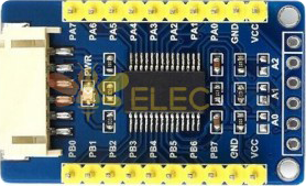
Pin Configuration and Descriptions

The MCP23017 has 28 pins, but the breakout board simplifies connections. Below is the pin configuration:

Pin Name Type Description
VDD Power Positive supply voltage (1.8V to 5.5V).
VSS Ground Ground connection.
SCL Input I2C clock line. Connect to the microcontroller's SCL pin.
SDA Input/Output I2C data line. Connect to the microcontroller's SDA pin.
A0, A1, A2 Input Address pins for configuring the I2C address (0x20 to 0x27).
INTA, INTB Output Interrupt outputs for GPIOA and GPIOB.
RESET Input Active-low reset pin. Pull high for normal operation.
GPA0-GPA7 Input/Output GPIO pins for Port A. Can be configured as input or output.
GPB0-GPB7 Input/Output GPIO pins for Port B. Can be configured as input or output.

Usage Instructions

How to Use the MCP23017 in a Circuit

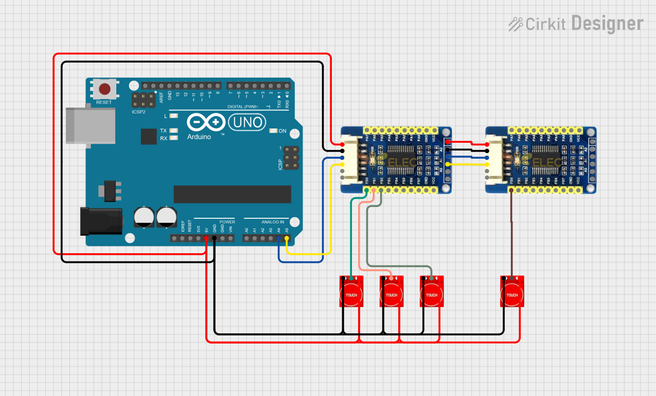
  1. Power the MCP23017: Connect the VDD pin to a 3.3V or 5V power source and the VSS pin to ground.
  2. Connect I2C Lines: Attach the SCL and SDA pins to the corresponding I2C pins on your microcontroller. Use pull-up resistors (typically 4.7 kΩ) on both lines if not already present.
  3. Set the I2C Address: Configure the A0, A1, and A2 pins to set the I2C address. For example:
    • All address pins grounded: Address = 0x20
    • A0 high, A1 and A2 low: Address = 0x21
  4. Configure GPIO Pins: Use the I2C protocol to set the direction (input/output) of each GPIO pin. You can also enable pull-up resistors or configure interrupt behavior.
  5. Read/Write Data: Use I2C commands to read from or write to the GPIO pins.

Important Considerations and Best Practices

  • Pull-Up Resistors: Ensure proper pull-up resistors are used on the I2C lines for reliable communication.
  • Interrupts: Use the INTA and INTB pins for interrupt-driven applications to avoid constant polling.
  • Voltage Levels: Match the MCP23017's operating voltage with your microcontroller's I2C voltage levels.
  • Address Conflicts: Avoid I2C address conflicts when using multiple devices on the same bus.

Example Code for Arduino UNO

Below is an example of how to use the MCP23017 with an Arduino UNO to control LEDs and read button inputs:

#include <Wire.h>
#include "Adafruit_MCP23017.h"

// Create an MCP23017 object
Adafruit_MCP23017 mcp;

void setup() {
  // Initialize I2C communication
  Wire.begin();

  // Initialize the MCP23017 at address 0x20
  mcp.begin(0);

  // Configure GPIOA0 as output (e.g., for an LED)
  mcp.pinMode(0, OUTPUT);

  // Configure GPIOA1 as input with pull-up resistor (e.g., for a button)
  mcp.pinMode(1, INPUT);
  mcp.pullUp(1, HIGH); // Enable pull-up resistor on GPIOA1

  // Start serial communication for debugging
  Serial.begin(9600);
}

void loop() {
  // Turn on the LED connected to GPIOA0
  mcp.digitalWrite(0, HIGH);

  // Check the button state on GPIOA1
  if (mcp.digitalRead(1) == LOW) {
    Serial.println("Button Pressed!");
  } else {
    Serial.println("Button Released!");
  }

  delay(500); // Wait for 500ms
}

Troubleshooting and FAQs

Common Issues and Solutions

  1. No Communication with MCP23017

    • Cause: Incorrect I2C address or wiring.
    • Solution: Verify the address pins (A0, A1, A2) and ensure proper connections to SDA and SCL.
  2. GPIO Pins Not Responding

    • Cause: Incorrect pin configuration.
    • Solution: Double-check the pinMode settings and ensure the pins are configured as input or output as needed.
  3. Interrupts Not Working

    • Cause: Interrupt pins not connected or misconfigured.
    • Solution: Ensure INTA/INTB pins are connected to the microcontroller and configure interrupt registers correctly.
  4. I2C Bus Errors

    • Cause: Missing pull-up resistors or incorrect voltage levels.
    • Solution: Add 4.7 kΩ pull-up resistors to SDA and SCL lines and ensure voltage compatibility.

FAQs

  • Can I use multiple MCP23017 devices on the same I2C bus? Yes, you can connect up to 8 MCP23017 devices by configuring their A0, A1, and A2 address pins.

  • What is the maximum current the GPIO pins can handle? Each GPIO pin can source or sink up to 25 mA, but the total current for all pins should not exceed 125 mA.

  • Do I need external pull-up resistors for the GPIO pins? No, the MCP23017 has programmable internal pull-up resistors, but you can use external ones if needed for specific applications.