How to Use Adafruit I2C QT Rotary Encoder: Examples, Pinouts, and Specs
Introduction
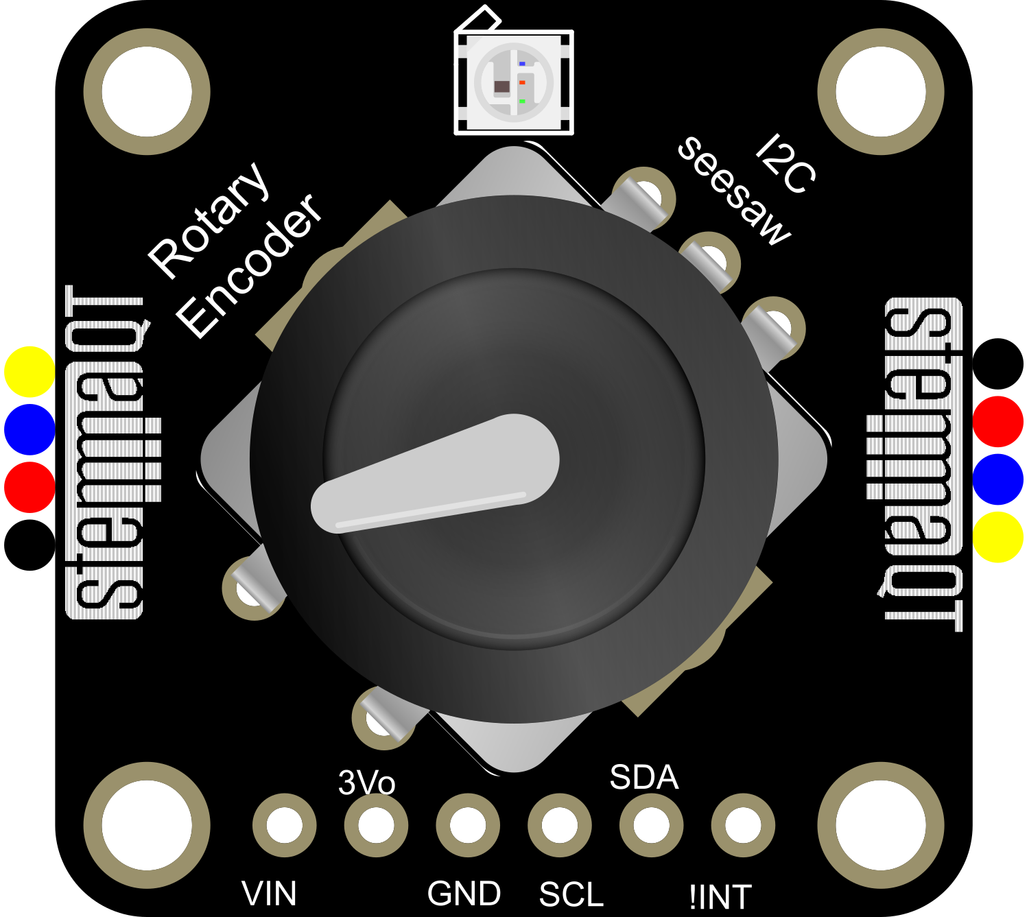
The Adafruit I2C QT Rotary Encoder is a versatile and user-friendly electronic component that enables precise tracking of rotary position and movement. It is designed to be interfaced with microcontrollers such as the Arduino UNO via the I2C communication protocol. This rotary encoder is ideal for applications such as user interfaces, menu navigation in projects, and volume control, among others.
Explore Projects Built with Adafruit I2C QT Rotary Encoder
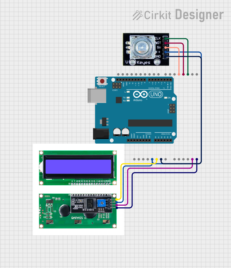
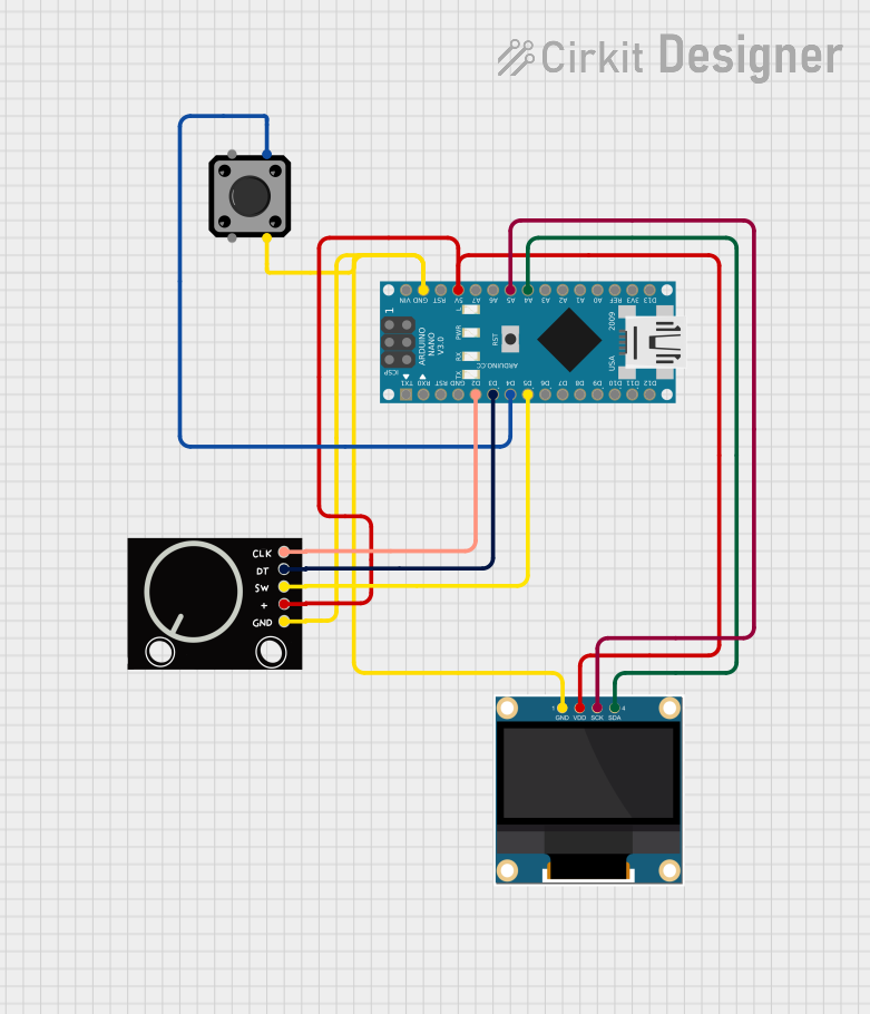

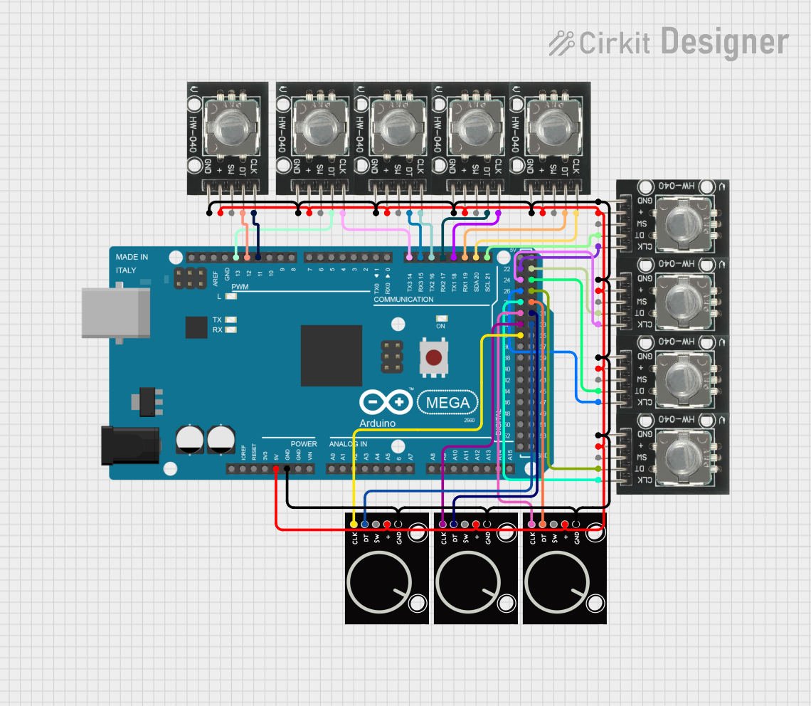
Explore Projects Built with Adafruit I2C QT Rotary Encoder
Technical Specifications
Key Technical Details
- Communication Interface: I2C
- Operating Voltage: 3.3V to 5V
- Resolution: 24 Pulses per Revolution
- Dimensions: 20mm x 20mm x 5mm
Pin Configuration and Descriptions
| Pin Number | Name | Description |
|---|---|---|
| 1 | VCC | Power supply (3.3V to 5V) |
| 2 | GND | Ground connection |
| 3 | SCL | I2C clock line |
| 4 | SDA | I2C data line |
| 5 | INT | Interrupt pin (optional use) |
Usage Instructions
Interfacing with Arduino
To use the Adafruit I2C QT Rotary Encoder with an Arduino UNO, follow these steps:
Connect the Encoder to the Arduino:
- Connect VCC to 5V on the Arduino.
- Connect GND to one of the GND pins on the Arduino.
- Connect SCL to the A5 pin (SCL) on the Arduino.
- Connect SDA to the A4 pin (SDA) on the Arduino.
- The INT pin can be connected to a digital pin if interrupt functionality is required.
Install the Adafruit Library:
- Use the Arduino Library Manager to install the
Adafruit Seesawlibrary, which is required to interface with the encoder.
- Use the Arduino Library Manager to install the
Programming the Arduino:
- Include the Adafruit Seesaw library in your sketch.
- Initialize the encoder and set up the I2C communication.
- Read the encoder position and button state in your main loop.
Example Arduino Sketch
#include <Wire.h>
#include <Adafruit_Seesaw.h>

Adafruit_Seesaw encoder;

void setup() {
  Serial.begin(9600);
  if (!encoder.begin(0x36)) { // Default I2C address is 0x36
    Serial.println("Encoder not found");
    while (1);
  }
  Serial.println("Encoder found!");
}

void loop() {
  int16_t position = encoder.encoderRead();
  Serial.print("Position: ");
  Serial.println(position);
  delay(100);
}
Important Considerations and Best Practices
- Ensure that the power supply voltage matches the operating voltage of the encoder.
- Use pull-up resistors on the SDA and SCL lines if they are not built into the microcontroller board.
- Avoid placing the encoder near high-power components that may cause electromagnetic interference.
- When using the interrupt pin, ensure that the microcontroller's interrupt pin is configured correctly in the sketch.
Troubleshooting and FAQs
Common Issues
- Encoder not responding: Check the wiring and ensure that the I2C address is correct.
- Inaccurate readings: Ensure that there is no electromagnetic interference and that the encoder is not mechanically obstructed.
- No output on serial monitor: Verify that the correct baud rate is set in the serial monitor and that the encoder is properly initialized in the code.
Solutions and Tips
- Double-check all connections and solder joints for reliability.
- Use the
Wire.setClock()function to adjust the I2C clock speed if necessary. - If using the interrupt pin, ensure that the microcontroller's interrupt service routine is not blocking or taking too long to execute.
FAQs
Q: Can I change the I2C address of the encoder? A: Yes, the I2C address can be changed by soldering the address jumpers on the back of the encoder.
Q: Is the encoder compatible with 3.3V systems? A: Yes, the encoder can operate at 3.3V, but ensure that the logic levels are compatible with the microcontroller.
Q: How do I use the button feature of the encoder?
A: The button state can be read using the encoder.readButton() function in the Adafruit Seesaw library.
For further assistance, consult the Adafruit I2C QT Rotary Encoder datasheet and the Adafruit Seesaw library documentation.