How to Use LM393: Examples, Pinouts, and Specs

Introduction
The LM393 is a dual independent precision voltage comparator, designed to operate from a single power supply over a wide range of voltages. It is capable of comparing two voltage inputs and providing a digital output to indicate which input is higher. This component is widely used in various applications such as sensor interfacing, voltage level detection, and threshold monitoring.
Explore Projects Built with LM393
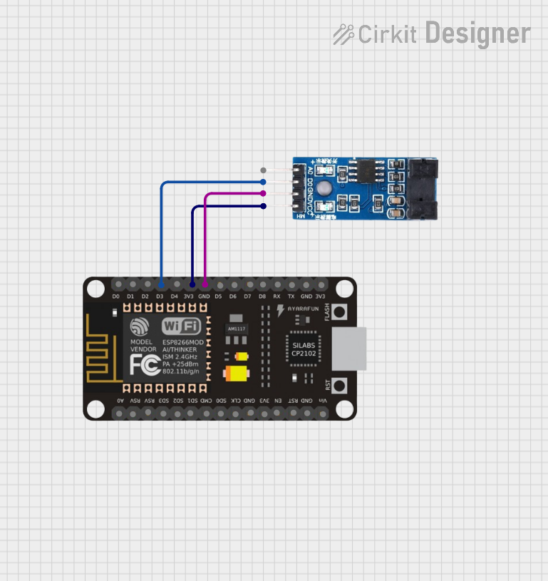
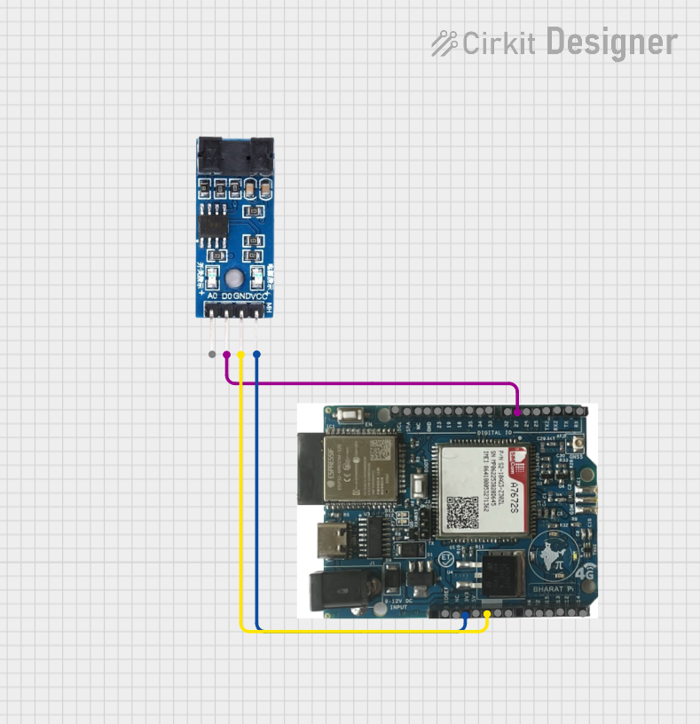


Explore Projects Built with LM393
Common Applications and Use Cases
- Battery chargers
- Voltage level monitoring
- Automotive sensors
- Motor control
- Logic voltage translation
- Window comparators
Technical Specifications
Key Technical Details
- Supply Voltage Range: 2.0V to 36V, or ±1.0V to ±18V (dual supplies)
- Input Bias Current: 25 nA (typical)
- Input Offset Current: ±5 nA (typical)
- Differential Input Voltage Range: Equal to the supply voltage
- Output Voltage Compatible with TTL, DTL, ECL, MOS, and CMOS logic systems
Pin Configuration and Descriptions
| Pin Number | Name | Description |
|---|---|---|
| 1 | OUT1 | Output of comparator 1 |
| 2 | IN1- | Inverting input of comparator 1 |
| 3 | IN1+ | Non-inverting input of comparator 1 |
| 4 | GND | Ground (0V) reference |
| 5 | IN2+ | Non-inverting input of comparator 2 |
| 6 | IN2- | Inverting input of comparator 2 |
| 7 | OUT2 | Output of comparator 2 |
| 8 | Vcc | Supply voltage |
Usage Instructions
How to Use the LM393 in a Circuit
Power Supply Connection: Connect the Vcc pin to a positive supply voltage within the specified range and the GND pin to the system ground.
Input Signal Connection: Apply the two voltages to be compared to the inverting (IN-) and non-inverting (IN+) inputs of the comparator.
Output Connection: The output can be connected to a digital logic input, or used to drive a transistor or relay with the appropriate external components.
Pull-up Resistor: The LM393 has an open-collector output, which requires an external pull-up resistor to the positive supply voltage to function correctly.
Important Considerations and Best Practices
- Ensure that the power supply voltage does not exceed the maximum rating of the IC.
- Avoid applying voltages to the input pins that exceed the supply voltage range.
- Use bypass capacitors close to the power supply pins to filter out noise.
- When interfacing with microcontrollers, ensure that the output voltage levels are compatible.
Example Circuit and Arduino Code
The following example demonstrates how to use the LM393 to compare a variable voltage with a fixed reference voltage and provide an output to an Arduino UNO.
// Define the Arduino pin connected to the LM393 output
const int comparatorOutputPin = 2;

void setup() {
  // Set the comparator output pin as an input
  pinMode(comparatorOutputPin, INPUT);
  // Begin serial communication at 9600 baud rate
  Serial.begin(9600);
}

void loop() {
  // Read the digital state of the comparator output
  int comparatorState = digitalRead(comparatorOutputPin);

  // Print the comparator state to the Serial Monitor
  Serial.println(comparatorState);
  delay(500); // Wait for half a second
}
Troubleshooting and FAQs
Common Issues Users Might Face
- No Output Signal: Ensure that the pull-up resistor is correctly connected and that the input voltages are within the specified range.
- Erratic Output: Place a bypass capacitor near the power supply pins to stabilize the operation.
Solutions and Tips for Troubleshooting
- Check Power Supply: Verify that the supply voltage is within the specified range and is stable.
- Inspect Connections: Ensure that all pins are properly soldered and connected.
- Pull-up Resistor: Confirm that the pull-up resistor value is appropriate for the supply voltage and load.
FAQs
Q: Can the LM393 operate with a single supply voltage? A: Yes, the LM393 is designed to operate with a single supply voltage.
Q: What is the purpose of the pull-up resistor on the output? A: The pull-up resistor is required to provide a high level on the output when the open-collector output is in the off state.
Q: Can the LM393 outputs be connected directly to a microcontroller? A: Yes, but ensure that the microcontroller's input voltage levels are compatible with the LM393's output levels.