How to Use SparkFun_Ublox SAM-M8Q: Examples, Pinouts, and Specs
Introduction
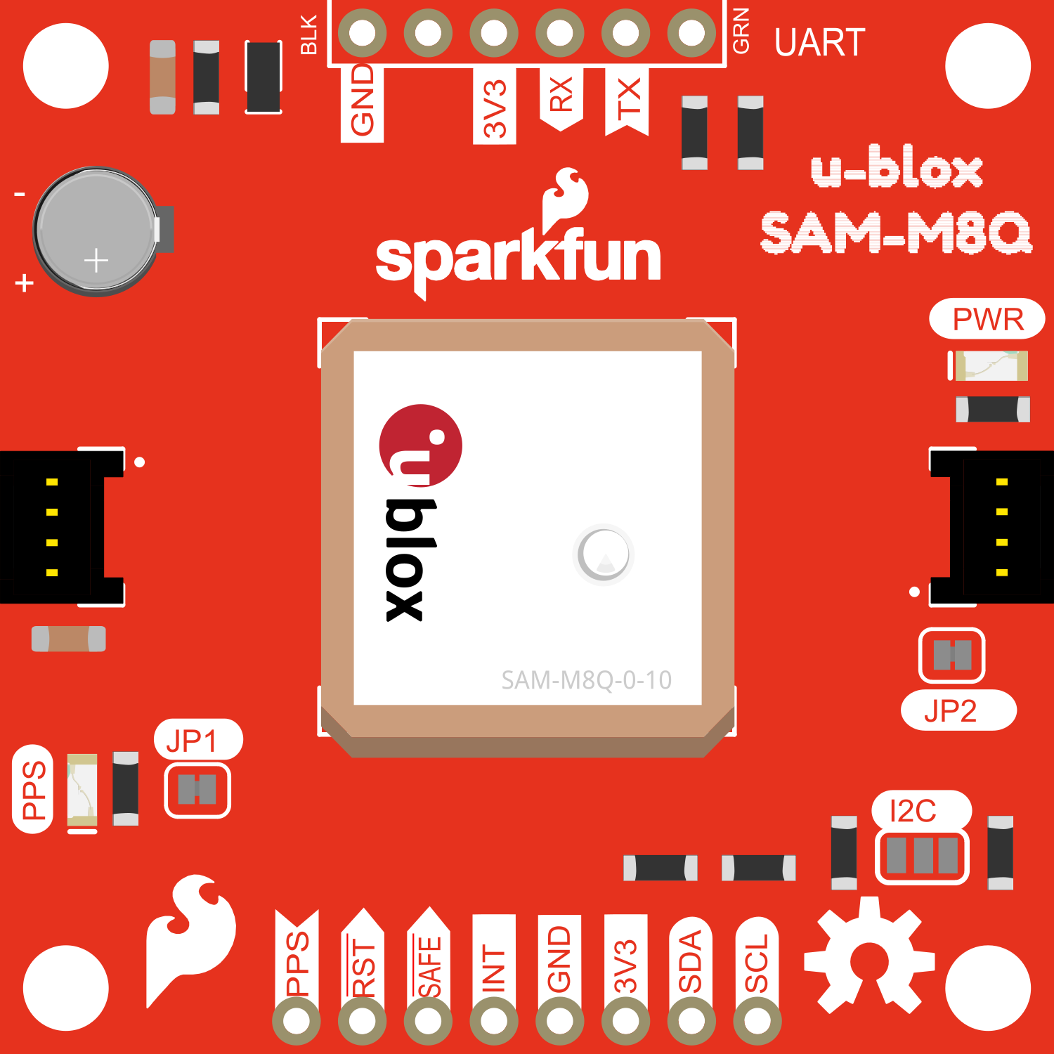
The SparkFun u-blox SAM-M8Q is a compact Global Positioning System (GPS) module that leverages the high performance of the u-blox M8 multi-GNSS (Global Navigation Satellite System) engine. This module is capable of receiving signals from multiple satellite constellations (GPS, GLONASS, Galileo) to provide accurate positioning and timing information. Common applications include navigation systems, asset tracking, UAVs (Unmanned Aerial Vehicles), and location-based services.
Explore Projects Built with SparkFun_Ublox SAM-M8Q

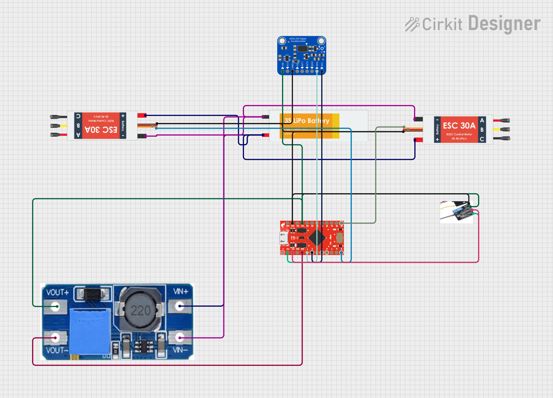
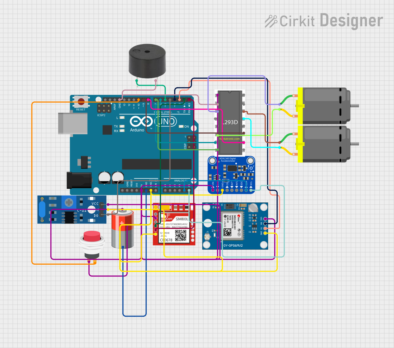
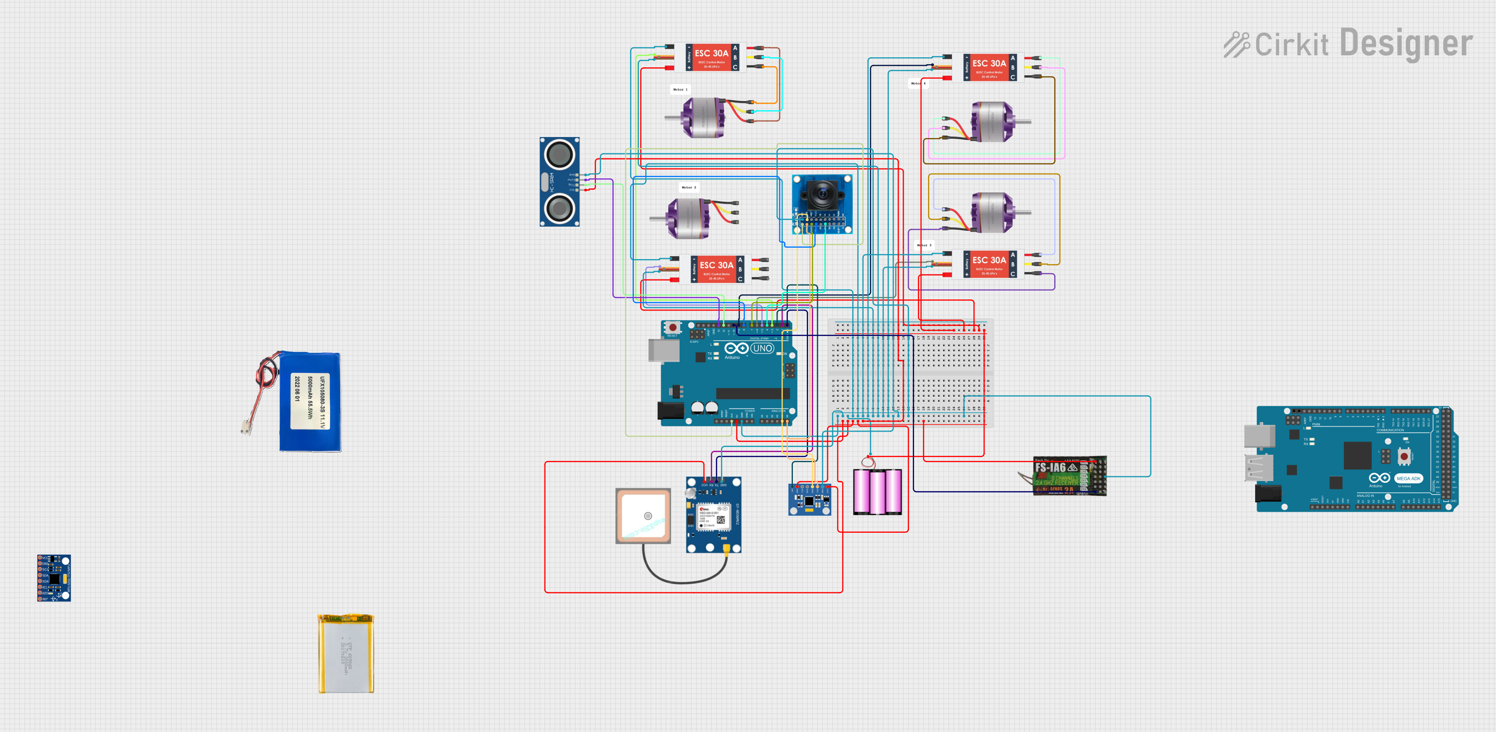
Explore Projects Built with SparkFun_Ublox SAM-M8Q
Technical Specifications
Key Technical Details
- Receiver Type: 72-channel u-blox M8 engine
- GNSS Support: GPS/QZSS L1 C/A, GLONASS L10F, BeiDou B1
- SBAS Support: WAAS, EGNOS, MSAS
- Horizontal Position Accuracy: 2.5 m (Autonomous), 2 m (SBAS)
- Update Rate: Up to 10 Hz
- Sensitivity: -167 dBm during navigation
- Time To First Fix: 26 s (Cold Start), 1 s (Hot Start)
- Operating Temperature: -40°C to 85°C
- Supply Voltage: 2.7V to 3.6V
- I/O Voltage: 1.7V to 3.6V
- Current Consumption: ~29 mA at 3.0V (Continuous Tracking)
Pin Configuration and Descriptions
| Pin Number | Name | Description |
|---|---|---|
| 1 | VCC | Power supply (2.7V to 3.6V) |
| 2 | GND | Ground connection |
| 3 | SDA | I2C Data |
| 4 | SCL | I2C Clock |
| 5 | TX | UART Transmit |
| 6 | RX | UART Receive |
| 7 | PPS | Pulse Per Second output |
Usage Instructions
Integration into a Circuit
To use the SAM-M8Q GPS module in a circuit:
- Connect the VCC pin to a power supply within the specified voltage range.
- Connect the GND pin to the ground of the power supply.
- For UART communication, connect the TX and RX pins to the corresponding RX and TX pins of the microcontroller.
- For I2C communication, connect the SDA and SCL pins to the I2C data and clock lines, respectively.
- Optionally, connect the PPS pin to an input on the microcontroller if pulse per second functionality is required.
Best Practices
- Ensure that the antenna has a clear view of the sky for optimal signal reception.
- Use proper decoupling capacitors close to the power supply pins to minimize power supply noise.
- Avoid placing the module near sources of electromagnetic interference.
- For UART communication, ensure that the baud rate of the microcontroller matches the default baud rate of the module.
Troubleshooting and FAQs
Common Issues
- No GPS Fix: Ensure the antenna is not obstructed and has a clear view of the sky. Check the power supply and wiring connections.
- Inaccurate Position: Wait for the module to receive signals from more satellites or check for sources of interference.
- Communication Failure: Verify the wiring for UART/I2C and ensure that the correct communication protocol and settings are being used.
Solutions and Tips
- Cold Start: If the module is taking too long to get a fix after being powered on, it may be experiencing a cold start. Ensure the module has a clear view of the sky and wait a few minutes.
- Interference: Keep the module away from electronic devices that may cause interference, such as motors or high-frequency signals.
FAQs
Q: Can the module be used indoors?
- A: GPS signals are significantly weakened indoors. The module is best used outdoors with a clear view of the sky.
Q: What is the default baud rate for UART communication?
- A: The default baud rate is typically 9600 bps, but it is recommended to check the module's datasheet for confirmation.
Q: How can I improve the time to first fix (TTFF)?
- A: Ensure the module has a clear view of the sky and is not moving. Additionally, using the module regularly in the same location can improve TTFF.
Example Code for Arduino UNO
Below is an example of how to interface the SAM-M8Q GPS module with an Arduino UNO using UART communication.
#include <SoftwareSerial.h>

// RX and TX pins connected to the Arduino
const int GPS_RX_PIN = 3;
const int GPS_TX_PIN = 4;

// Set up the software serial port
SoftwareSerial gpsSerial(GPS_RX_PIN, GPS_TX_PIN);

void setup() {
  // Start the serial communication
  Serial.begin(9600);
  gpsSerial.begin(9600); // SAM-M8Q default baud rate
  Serial.println("GPS Module Test");
}

void loop() {
  // Check if data is available from the GPS module
  if (gpsSerial.available()) {
    // Read the data and print it to the serial monitor
    Serial.write(gpsSerial.read());
  }
}
Remember to wrap the GPS module's TX pin to the Arduino's RX pin and vice versa. The SoftwareSerial library allows for serial communication on other digital pins of the Arduino, as the hardware serial port is often used for debugging and uploading sketches.