The LM393 Hall Effect Sensor Module is a versatile electronic component designed to detect magnetic fields using the Hall effect principle. It provides a digital output signal that indicates the presence or absence of a magnetic object. This module is widely used in applications such as proximity detection, speed measurement, position sensing, and magnetic field detection.
Explore Projects Built with LM393 Hall Effect Sensor Module
Use Cirkit Designer to design, explore, and prototype these projects online. Some projects support real-time simulation. Click "Open Project" to start designing instantly!
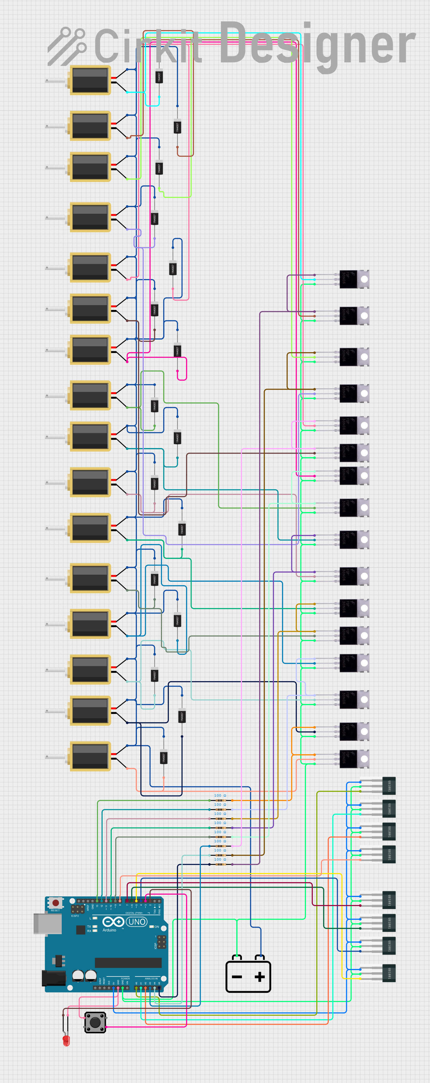
This circuit is designed to use Hall effect sensors for magnetic field detection, interfaced with an Arduino UNO microcontroller to control an array of solenoids through MOSFETs. It includes user interface elements such as a tactile switch and LED, and features flyback diodes for solenoid protection.
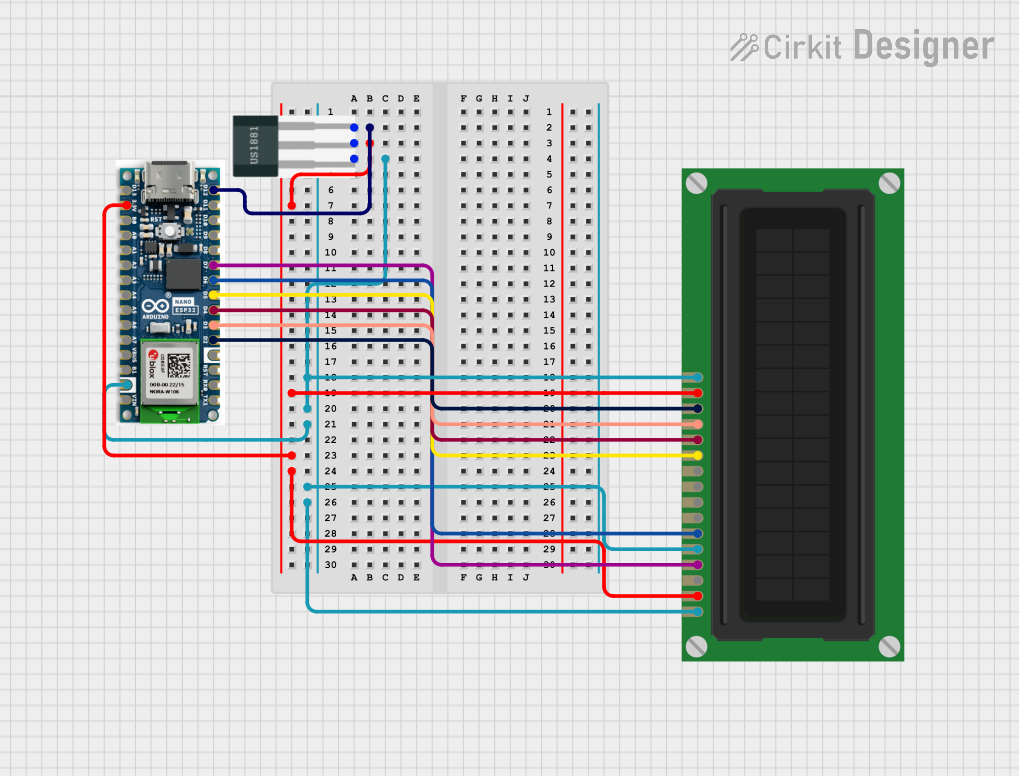
This circuit includes a Hall sensor connected to an Arduino Nano ESP32 microcontroller, which is likely used to detect magnetic fields and send the data to the microcontroller on pin D12. The Arduino is also interfaced with an LCD display, with connections for power, ground, control (RS, E), and data (DB4-DB7) to display information. The absence of code suggests that the microcontroller's behavior is not defined in this context, but it is set up to read the Hall sensor and output to the LCD.
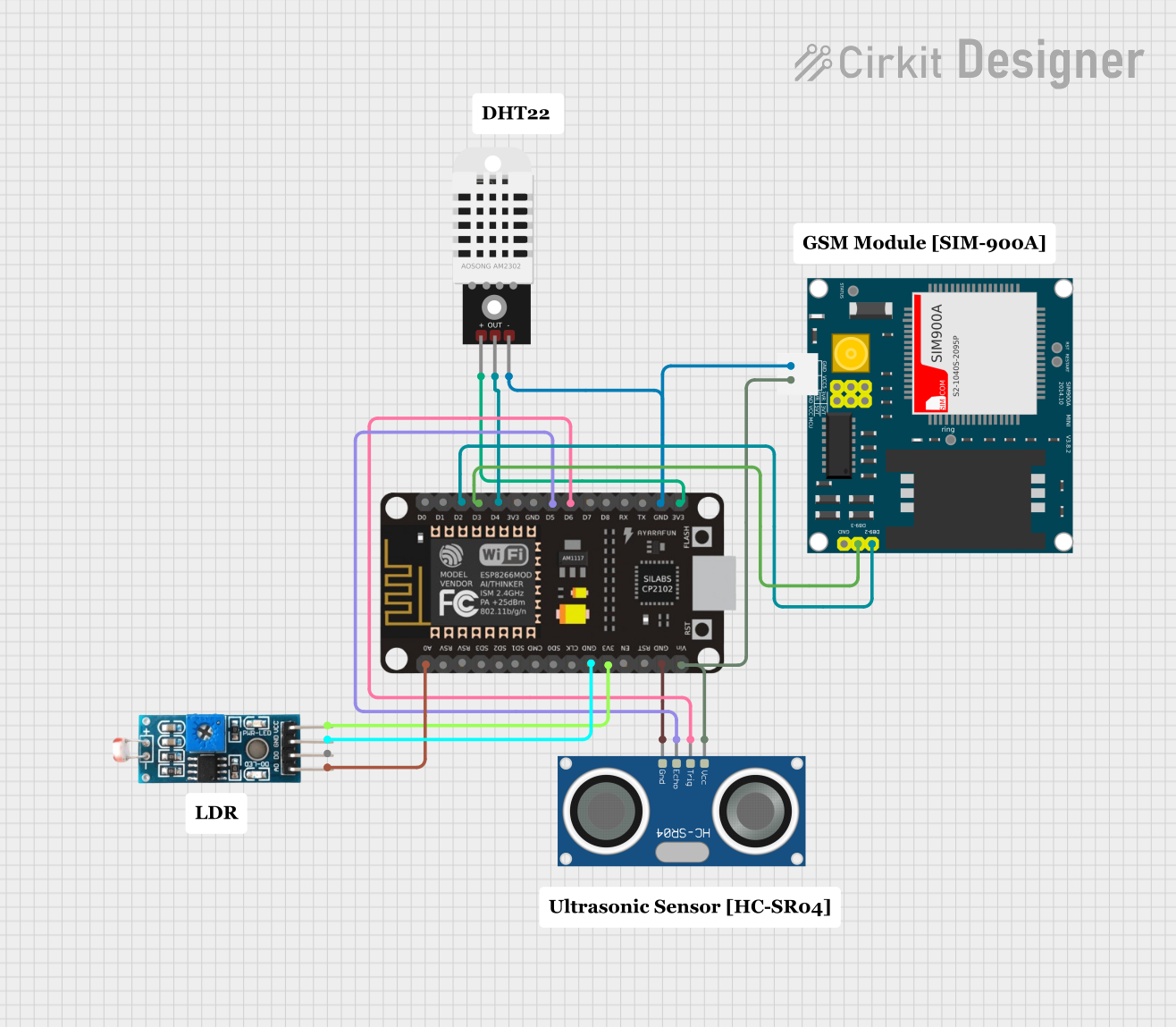
This is a sensor-based data acquisition system with GSM communication capability. It uses an ESP8266 NodeMCU to collect environmental data from a DHT22 sensor and light levels from an LDR, as well as distance measurements from an HC-SR04 ultrasonic sensor. The SIM900A GSM module enables the system to transmit the collected data over a cellular network.
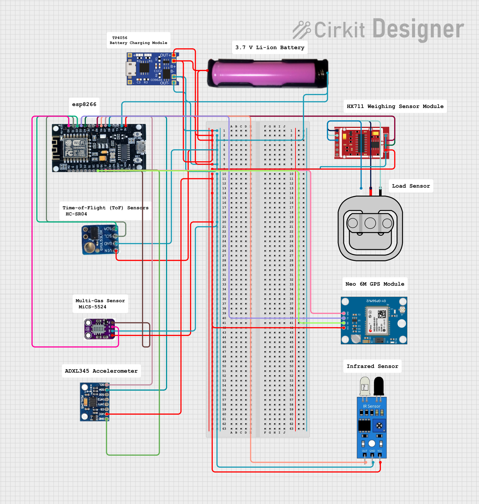
This circuit is a multi-sensor data acquisition system powered by a 18650 battery and managed by an ESP8266 microcontroller. It includes a load sensor interfaced with an HX711 module for weight measurement, an IR sensor, an ADXL345 accelerometer, a VL53L0X distance sensor, and a Neo 6M GPS module for location tracking. The system is designed for wireless data transmission and is supported by a TP4056 module for battery charging.
Proximity Sensors: Detecting the presence of magnetic objects in industrial or consumer devices.
Speed Measurement: Monitoring the rotational speed of motors or wheels.
Position Sensing: Determining the position of moving parts in machinery.
Magnetic Field Detection: Identifying the presence of magnetic fields in scientific or educational experiments.
Technical Specifications
The LM393 Hall Effect Sensor Module is based on the LM393 comparator IC and a Hall effect sensor. Below are the key technical details:
Key Technical Details
Operating Voltage: 3.3V to 5V DC
Output Type: Digital (High/Low)
Output Current: 15mA (maximum)
Sensitivity: Detects magnetic fields with a north or south pole
Response Time: Fast response to changes in the magnetic field
Operating Temperature: -40°C to +85°C
Dimensions: Compact module design for easy integration
Pin Configuration and Descriptions
The LM393 Hall Effect Sensor Module typically has three pins. The table below describes each pin:
Pin Name
Pin Number
Description
VCC
1
Power supply input (3.3V to 5V DC)
GND
2
Ground connection
OUT
3
Digital output signal (High/Low)
Usage Instructions
How to Use the Component in a Circuit
Power the Module: Connect the VCC pin to a 3.3V or 5V DC power source and the GND pin to the ground of your circuit.
Connect the Output: Attach the OUT pin to a digital input pin of a microcontroller (e.g., Arduino UNO) or to an external circuit for further processing.
Place a Magnet: Position a magnetic object near the Hall effect sensor. The module will output a digital signal (High or Low) based on the presence or absence of the magnetic field.
Important Considerations and Best Practices
Magnet Orientation: Ensure the magnet's pole is aligned correctly with the sensor for accurate detection.
Power Supply: Use a stable power source to avoid erratic behavior.
Distance Sensitivity: The detection range depends on the strength of the magnetic field. Test the module with your specific magnet to determine the optimal distance.
Debouncing: If the output signal fluctuates, consider adding a software debounce routine in your microcontroller code.
Example Code for Arduino UNO
Below is an example of how to use the LM393 Hall Effect Sensor Module with an Arduino UNO:
// LM393 Hall Effect Sensor Module Example Code
// Connect the OUT pin of the module to Arduino digital pin 2

const int hallSensorPin = 2; // Pin connected to the OUT pin of the sensor
const int ledPin = 13;       // Pin connected to the onboard LED

void setup() {
  pinMode(hallSensorPin, INPUT); // Set the sensor pin as input
  pinMode(ledPin, OUTPUT);       // Set the LED pin as output
  Serial.begin(9600);           // Initialize serial communication
}

void loop() {
  int sensorState = digitalRead(hallSensorPin); // Read the sensor output

  if (sensorState == HIGH) {
    // Magnetic field detected
    digitalWrite(ledPin, HIGH); // Turn on the LED
    Serial.println("Magnetic field detected!");
  } else {
    // No magnetic field detected
    digitalWrite(ledPin, LOW);  // Turn off the LED
    Serial.println("No magnetic field detected.");
  }

  delay(100); // Small delay for stability
}
Troubleshooting and FAQs
Common Issues and Solutions
No Output Signal:
Cause: Incorrect wiring or loose connections.
Solution: Double-check the connections, ensuring the VCC, GND, and OUT pins are properly connected.
Erratic Output:
Cause: Unstable power supply or interference.
Solution: Use a decoupling capacitor (e.g., 0.1µF) across the power supply pins to stabilize the voltage.
Low Sensitivity:
Cause: Weak magnetic field or incorrect magnet orientation.
Solution: Use a stronger magnet or adjust the orientation for better detection.
Output Always High or Low:
Cause: Faulty module or damaged Hall effect sensor.
Solution: Test the module with a known working magnet. Replace the module if necessary.
FAQs
Q: Can the LM393 Hall Effect Sensor Module detect both north and south poles of a magnet?
A: Yes, the module can detect the presence of a magnetic field regardless of the pole orientation.
Q: What is the maximum detection range of the module?
A: The detection range depends on the strength of the magnetic field. Typically, it ranges from a few millimeters to several centimeters.
Q: Can I use this module with a 3.3V microcontroller?
A: Yes, the module operates within a voltage range of 3.3V to 5V, making it compatible with 3.3V microcontrollers.
Q: Is the module suitable for outdoor use?
A: The module is not weatherproof. If used outdoors, ensure it is enclosed in a protective casing to prevent damage from moisture or dust.


 Open Project in Cirkit Designer