Cirkit Designer
Your all-in-one circuit design IDE
Home /
Component Documentation
How to Use P10 LED Matrix Panel: Examples, Pinouts, and Specs
Introduction
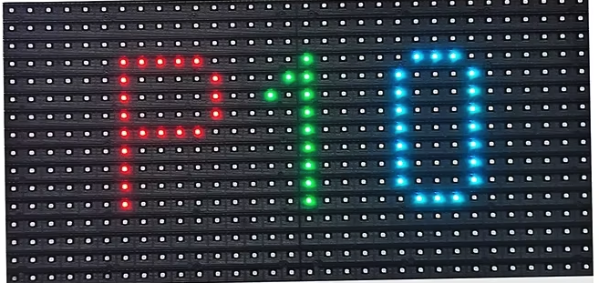
The P10 LED Matrix Panel is a display module consisting of a grid of LEDs arranged in a 32x16 matrix. Manufactured by Arduino, this panel is commonly used for creating large, bright, and colorful displays for advertising, information boards, and other visual applications. The panel can be controlled using various microcontrollers and is capable of displaying text, images, and animations.
Explore Projects Built with P10 LED Matrix Panel
Voice-Controlled P10 LED Matrix Display with Arduino and Bluetooth
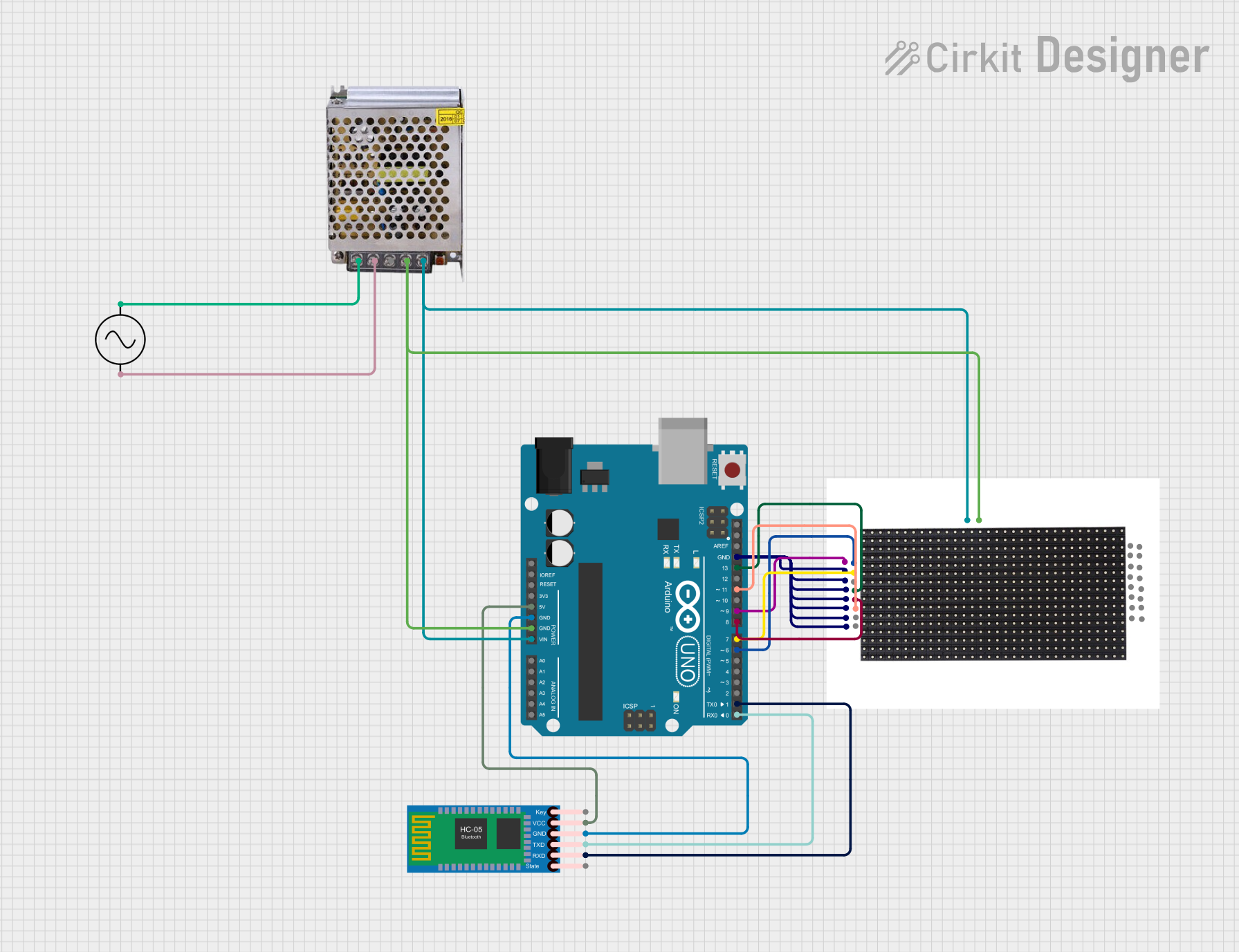
This circuit features an Arduino UNO microcontroller interfaced with a 16x32 P10 LED matrix display and an HC-05 Bluetooth module. The Arduino receives voice commands via Bluetooth, processes them, and controls the LED matrix to display corresponding messages. A 5V power supply provides power to the Arduino and the LED matrix, while the AC supply is converted to DC for the power supply unit.
Arduino UNO Controlled LED Matrix and LCD Interface with Joystick Interaction

This circuit features an Arduino UNO microcontroller interfaced with an 8x8 LED matrix, an LCD screen, and a KY-023 Dual Axis Joystick Module. The Arduino controls the LED matrix via digital pins D10-D12 and powers the matrix, LCD, and joystick module from its 5V output. The joystick's analog outputs are connected to the Arduino's analog inputs A0 and A1 for position sensing, while the LCD is controlled through digital pins D2-D6 and D13 for display purposes.
Arduino UNO Controlled 8x8 LED Matrix Display
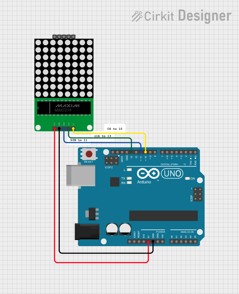
This circuit consists of an Arduino UNO microcontroller connected to a MAX7219 8x8 LED Matrix. The Arduino controls the LED matrix by sending data through digital pins D10, D11, and D13, while power and ground connections are provided by the 5V and GND pins, respectively.
Arduino UNO Controlled LED Matrix Display with Interactive Pushbuttons
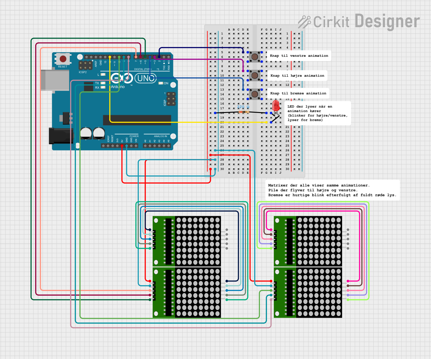
This circuit features an Arduino UNO microcontroller connected to multiple 8x8 LED matrix displays and pushbuttons. The pushbuttons are interfaced with digital pins D2, D3, and D4 on the Arduino for input, while the LED matrices are connected to digital pins D5 through D10 for control signals. Additionally, there is a single red LED with a series resistor connected to pin D12, likely used as an indicator light.
Explore Projects Built with P10 LED Matrix Panel
Voice-Controlled P10 LED Matrix Display with Arduino and Bluetooth
This circuit features an Arduino UNO microcontroller interfaced with a 16x32 P10 LED matrix display and an HC-05 Bluetooth module. The Arduino receives voice commands via Bluetooth, processes them, and controls the LED matrix to display corresponding messages. A 5V power supply provides power to the Arduino and the LED matrix, while the AC supply is converted to DC for the power supply unit.
Arduino UNO Controlled LED Matrix and LCD Interface with Joystick Interaction
This circuit features an Arduino UNO microcontroller interfaced with an 8x8 LED matrix, an LCD screen, and a KY-023 Dual Axis Joystick Module. The Arduino controls the LED matrix via digital pins D10-D12 and powers the matrix, LCD, and joystick module from its 5V output. The joystick's analog outputs are connected to the Arduino's analog inputs A0 and A1 for position sensing, while the LCD is controlled through digital pins D2-D6 and D13 for display purposes.
Arduino UNO Controlled 8x8 LED Matrix Display
This circuit consists of an Arduino UNO microcontroller connected to a MAX7219 8x8 LED Matrix. The Arduino controls the LED matrix by sending data through digital pins D10, D11, and D13, while power and ground connections are provided by the 5V and GND pins, respectively.
Arduino UNO Controlled LED Matrix Display with Interactive Pushbuttons
This circuit features an Arduino UNO microcontroller connected to multiple 8x8 LED matrix displays and pushbuttons. The pushbuttons are interfaced with digital pins D2, D3, and D4 on the Arduino for input, while the LED matrices are connected to digital pins D5 through D10 for control signals. Additionally, there is a single red LED with a series resistor connected to pin D12, likely used as an indicator light.
Technical Specifications
Key Technical Details
| Specification | Value |
|---|---|
| Manufacturer | Arduino |
| Part ID | P10 LED Matrix Panel |
| LED Configuration | 32x16 |
| Operating Voltage | 5V DC |
| Power Consumption | 20W |
| Interface | HUB75 |
| Pixel Pitch | 10mm |
| Brightness | 1200-1500 cd/m² |
| Viewing Angle | 140° (Horizontal), 140° (Vertical) |
| Dimensions | 320mm x 160mm x 15mm |
Pin Configuration and Descriptions
| Pin Number | Pin Name | Description |
|---|---|---|
| 1 | GND | Ground |
| 2 | A | Row Address A |
| 3 | B | Row Address B |
| 4 | C | Row Address C |
| 5 | D | Row Address D |
| 6 | CLK | Clock Signal |
| 7 | LAT | Latch Signal |
| 8 | OE | Output Enable |
| 9 | R1 | Red Data for Upper Half |
| 10 | G1 | Green Data for Upper Half |
| 11 | B1 | Blue Data for Upper Half |
| 12 | R2 | Red Data for Lower Half |
| 13 | G2 | Green Data for Lower Half |
| 14 | B2 | Blue Data for Lower Half |
| 15 | VCC | Power Supply (5V) |
Usage Instructions
How to Use the Component in a Circuit
- Power Supply: Connect the VCC pin to a 5V power supply and the GND pin to the ground.
- Data Connections: Connect the data pins (R1, G1, B1, R2, G2, B2) to the corresponding data output pins of your microcontroller.
- Control Signals: Connect the control pins (A, B, C, D, CLK, LAT, OE) to the appropriate control pins on your microcontroller.
- Programming: Use a suitable library (e.g., PxMatrix for Arduino) to control the display.
Important Considerations and Best Practices
- Power Supply: Ensure that your power supply can provide sufficient current (at least 4A) to the panel.
- Heat Management: The panel can get warm during operation; ensure adequate ventilation.
- Signal Integrity: Use short and well-routed wires to minimize signal degradation.
- Library: Use a well-supported library like PxMatrix for easier control and better performance.
Example Code for Arduino UNO
#include <PxMatrix.h>

// Pins for the LED matrix panel
#define P_LAT 10
#define P_A 11
#define P_B 12
#define P_C 13
#define P_D A0
#define P_OE 9

// Create a PxMatrix object
PxMatrix display(32, 16, P_LAT, P_OE, P_A, P_B, P_C, P_D);

void setup() {
  // Initialize the display
  display.begin(8);
  display.setBrightness(255);
  display.clearDisplay();
}

void loop() {
  // Display a simple text
  display.setTextColor(display.color565(255, 0, 0));
  display.setCursor(0, 0);
  display.print("Hello, World!");
  display.showBuffer();
  delay(1000);

  // Clear the display
  display.clearDisplay();
  display.showBuffer();
  delay(1000);
}
Troubleshooting and FAQs
Common Issues Users Might Face
- No Display Output: Ensure all connections are secure and the power supply is adequate.
- Flickering Display: Check for loose connections and ensure the control signals are stable.
- Dim LEDs: Verify that the brightness setting in the code is set correctly and the power supply is sufficient.
Solutions and Tips for Troubleshooting
- Check Connections: Double-check all wiring and connections to ensure they are correct and secure.
- Power Supply: Use a stable and adequate power supply to avoid power-related issues.
- Library and Code: Ensure you are using a compatible library and that your code is correctly configured for the panel.
By following this documentation, users should be able to effectively utilize the P10 LED Matrix Panel in their projects, whether they are beginners or experienced users.