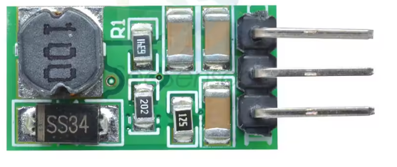
How to Use DD4012SA step-down regulator: Examples, Pinouts, and Specs
Introduction
The DD4012SA is a high-efficiency DC-DC step-down regulator manufactured by MICRONE. It is designed to convert a higher input voltage into a stable, lower output voltage, making it ideal for powering low-voltage devices from higher-voltage sources. This regulator is widely used in applications such as battery-powered systems, industrial equipment, and embedded electronics.
Explore Projects Built with DD4012SA step-down regulator


Explore Projects Built with DD4012SA step-down regulator
Common Applications
- Powering microcontrollers and sensors in embedded systems
- Voltage regulation in battery-operated devices
- Industrial automation and control systems
- Consumer electronics requiring stable low-voltage power
Technical Specifications
The following table outlines the key technical specifications of the DD4012SA:
| Parameter | Value |
|---|---|
| Input Voltage Range | 8V to 40V |
| Output Voltage Range | 1.25V to 12V |
| Maximum Output Current | 2A |
| Efficiency | Up to 95% |
| Switching Frequency | 150 kHz |
| Operating Temperature | -40°C to +85°C |
| Package Type | TO-252-5L |
Pin Configuration and Descriptions
The DD4012SA comes in a TO-252-5L package with the following pinout:
| Pin Number | Pin Name | Description |
|---|---|---|
| 1 | VIN | Input voltage (8V to 40V) |
| 2 | GND | Ground connection |
| 3 | SW | Switching node (connects to the inductor) |
| 4 | FB | Feedback pin (used to set the output voltage) |
| 5 | EN | Enable pin (active high, enables the regulator) |
Usage Instructions
How to Use the DD4012SA in a Circuit
- Input Voltage: Connect a DC voltage source (8V to 40V) to the VIN pin. Ensure the input voltage is within the specified range.
- Output Voltage Setting: Use a resistor divider network connected to the FB pin to set the desired output voltage. The output voltage can be calculated using the formula: [ V_{OUT} = V_{REF} \times \left(1 + \frac{R1}{R2}\right) ] where ( V_{REF} ) is typically 1.25V.
- Inductor and Capacitor Selection: Choose an appropriate inductor and output capacitor based on the desired output voltage and current. Refer to the datasheet for recommended values.
- Enable Pin: Connect the EN pin to a logic high signal (or VIN) to enable the regulator. Pulling this pin low disables the regulator.
- Switching Node: Connect the SW pin to the inductor and diode as part of the step-down circuit.
Important Considerations
- Thermal Management: Ensure proper heat dissipation by using a heatsink or adequate PCB copper area around the regulator.
- Input Capacitor: Place a low-ESR capacitor close to the VIN pin to reduce input voltage ripple.
- Output Ripple: Use a low-ESR output capacitor to minimize output voltage ripple.
- PCB Layout: Keep the feedback trace short and away from noisy nodes like the switching node.
Example: Using DD4012SA with Arduino UNO
The DD4012SA can be used to power an Arduino UNO from a 12V battery. Below is an example circuit and Arduino code to demonstrate its usage:
Circuit Setup
- Connect the 12V battery to the VIN pin of the DD4012SA.
- Set the output voltage to 5V using a resistor divider network.
- Connect the 5V output to the Arduino UNO's 5V pin.
Arduino Code Example
// Example code to blink an LED using Arduino UNO powered by DD4012SA
const int ledPin = 13; // Pin connected to the onboard LED

void setup() {
  pinMode(ledPin, OUTPUT); // Set the LED pin as an output
}

void loop() {
  digitalWrite(ledPin, HIGH); // Turn the LED on
  delay(1000);                // Wait for 1 second
  digitalWrite(ledPin, LOW);  // Turn the LED off
  delay(1000);                // Wait for 1 second
}
Troubleshooting and FAQs
Common Issues and Solutions
No Output Voltage
- Ensure the EN pin is connected to a logic high signal.
- Verify the input voltage is within the specified range (8V to 40V).
- Check for proper connections and soldering.
Excessive Heat
- Ensure the regulator is not overloaded (current > 2A).
- Improve heat dissipation by adding a heatsink or increasing PCB copper area.
High Output Ripple
- Use low-ESR capacitors for input and output filtering.
- Verify the inductor value is appropriate for the load current.
Incorrect Output Voltage
- Check the resistor divider network connected to the FB pin.
- Ensure the feedback trace is short and away from noisy nodes.
FAQs
Q: Can the DD4012SA be used with a 24V input?
A: Yes, the DD4012SA supports input voltages up to 40V, so 24V is within the acceptable range.
Q: What is the maximum output current?
A: The DD4012SA can provide a maximum output current of 2A.
Q: How do I calculate the resistor values for the feedback network?
A: Use the formula ( V_{OUT} = V_{REF} \times \left(1 + \frac{R1}{R2}\right) ), where ( V_{REF} = 1.25V ).
Q: Can I disable the regulator?
A: Yes, pulling the EN pin low will disable the regulator.
This concludes the documentation for the DD4012SA Step-Down Regulator. For further details, refer to the official datasheet provided by MICRONE.