
How to Use STM32F103C8T6 Blue Pill: Examples, Pinouts, and Specs
 Design with STM32F103C8T6 Blue Pill in Cirkit Designer
Introduction
The STM32F103C8T6 Blue Pill is a compact and affordable microcontroller board based on the STM32F103C8T6 chip. It features a 32-bit ARM Cortex-M3 core, 64KB of flash memory, and a wide range of I/O pins, making it a versatile choice for embedded systems and IoT projects. Its small form factor and low cost make it popular among hobbyists and professionals alike.
Explore Projects Built with STM32F103C8T6 Blue Pill
 Open Project in Cirkit Designer
 Open Project in Cirkit Designer
 Open Project in Cirkit Designer
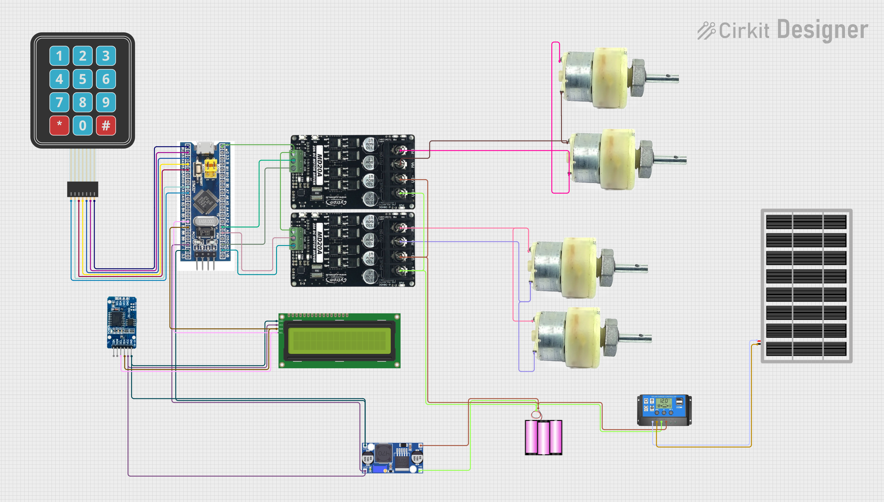 Open Project in Cirkit Designer
Explore Projects Built with STM32F103C8T6 Blue Pill
Open Project in Cirkit DesignerOpen Project in Cirkit DesignerOpen Project in Cirkit DesignerOpen Project in Cirkit DesignerCommon Applications and Use Cases
- Robotics and automation systems
- IoT devices and smart home applications
- Data acquisition and sensor interfacing
- Prototyping and educational projects
- Motor control and signal processing
Technical Specifications
Key Technical Details
| Parameter | Value |
|---|---|
| Microcontroller | STM32F103C8T6 |
| Core | ARM Cortex-M3 |
| Operating Voltage | 3.3V |
| Flash Memory | 64KB |
| SRAM | 20KB |
| Clock Speed | 72 MHz |
| GPIO Pins | 37 |
| Communication Interfaces | UART, SPI, I2C, CAN, USB |
| ADC Channels | 10 (12-bit resolution) |
| PWM Channels | 15 |
| Power Supply | 5V via USB or 3.3V via onboard regulator |
Pin Configuration and Descriptions
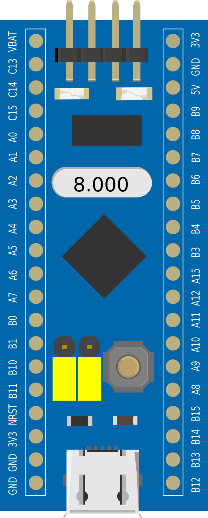
The STM32F103C8T6 Blue Pill has a total of 40 pins, including power, ground, and I/O pins. Below is a summary of the pin configuration:
| Pin Number | Label | Description |
|---|---|---|
| 1 | 3.3V | 3.3V power output |
| 2 | GND | Ground |
| 3 | A0 - A7 | Analog input pins (12-bit ADC) |
| 4 | D0 - D15 | Digital I/O pins |
| 5 | TX, RX | UART communication pins |
| 6 | SCL, SDA | I2C communication pins |
| 7 | USB+ / USB- | USB data lines |
| 8 | NRST | Reset pin |
| 9 | BOOT0 | Boot mode selection |
| 10 | 5V | 5V power input |
Usage Instructions
How to Use the STM32F103C8T6 Blue Pill in a Circuit
Powering the Board:
- Connect the board to a 5V power source via the USB port or supply 3.3V directly to the 3.3V pin.
- Ensure the ground (GND) pin is connected to the circuit's ground.
Programming the Board:
- Use a USB-to-Serial adapter or an ST-Link programmer to upload code.
- Set the BOOT0 pin to
1(high) for programming mode and back to0(low) for normal operation.
Connecting Peripherals:
- Use the GPIO pins for interfacing with sensors, actuators, or other devices.
- For analog inputs, connect sensors to the A0-A7 pins.
- For communication, use the UART, SPI, or I2C pins as needed.
Flashing Code:
- Install the STM32CubeIDE or Arduino IDE with the STM32 core.
- Write your code and upload it to the board using the appropriate programmer.
Important Considerations and Best Practices
- Always use a voltage level shifter when interfacing 5V devices with the 3.3V GPIO pins.
- Avoid drawing more than 25mA from any GPIO pin to prevent damage.
- Use decoupling capacitors near the power pins to reduce noise.
- Ensure proper grounding to avoid erratic behavior in high-speed applications.
Example Code for Arduino IDE
Below is an example of blinking an LED connected to pin PC13:
// Include the STM32 core library
#include <Arduino.h>

// Define the LED pin (PC13 is onboard LED on Blue Pill)
#define LED_PIN PC13

void setup() {
  pinMode(LED_PIN, OUTPUT); // Set LED pin as output
}

void loop() {
  digitalWrite(LED_PIN, HIGH); // Turn LED on
  delay(500);                  // Wait for 500ms
  digitalWrite(LED_PIN, LOW);  // Turn LED off
  delay(500);                  // Wait for 500ms
}
Troubleshooting and FAQs
Common Issues and Solutions
Board Not Detected by Programmer:
- Ensure the BOOT0 pin is set to
1for programming mode. - Check the USB cable and connections.
- Verify that the correct COM port is selected in the IDE.
- Ensure the BOOT0 pin is set to
Code Upload Fails:
- Ensure the correct board and programmer are selected in the IDE.
- Press the reset button before uploading the code.
GPIO Pins Not Responding:
- Check for proper pinMode configuration in the code.
- Verify that the connected device is functioning correctly.
Board Overheating:
- Ensure the power supply voltage does not exceed the recommended range.
- Avoid drawing excessive current from the GPIO pins.
FAQs
Q: Can I use the STM32F103C8T6 Blue Pill with the Arduino IDE?
A: Yes, you can use the Arduino IDE by installing the STM32 core. Follow the instructions on the STM32 Arduino GitHub page.
Q: What is the maximum clock speed of the Blue Pill?
A: The maximum clock speed is 72 MHz.
Q: How do I select between USB and UART for programming?
A: Use the BOOT0 pin to select the boot mode. For USB programming, ensure the correct drivers are installed.
Q: Can I power the board with 5V?
A: Yes, you can power the board via the USB port or the 5V pin. However, the GPIO pins operate at 3.3V, so use level shifters if interfacing with 5V devices.