
How to Use TRIMPOT: Examples, Pinouts, and Specs
 Design with TRIMPOT in Cirkit Designer
Introduction
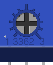
A trimmer potentiometer, commonly referred to as a trimpot, is a small adjustable resistor used to calibrate or fine-tune electronic circuits. It typically features three terminals and allows for precise adjustments of resistance, making it an essential component in applications where fine control of voltage or current is required. Trimpots are widely used in devices such as amplifiers, sensors, and oscillators to ensure optimal performance.
Explore Projects Built with TRIMPOT
 Open Project in Cirkit Designer
 Open Project in Cirkit Designer
 Open Project in Cirkit Designer
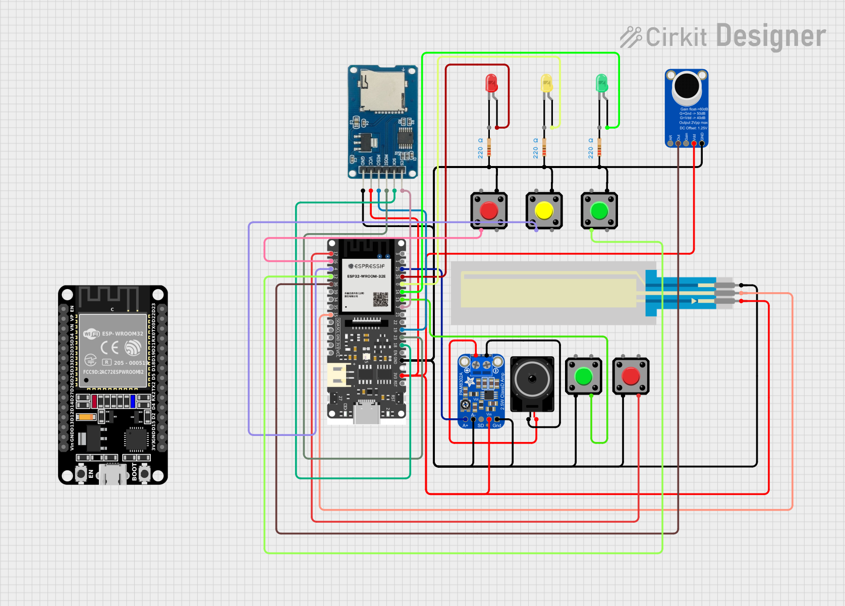 Open Project in Cirkit Designer
Explore Projects Built with TRIMPOT
Open Project in Cirkit DesignerOpen Project in Cirkit DesignerOpen Project in Cirkit DesignerOpen Project in Cirkit DesignerCommon Applications and Use Cases
- Calibration of analog circuits
- Adjusting sensitivity in sensors
- Fine-tuning voltage dividers
- Setting reference voltages in operational amplifiers
- Balancing bridge circuits
Technical Specifications
Below are the general technical specifications for a standard trimpot. Note that specific values may vary depending on the model and manufacturer.
| Parameter | Specification |
|---|---|
| Resistance Range | 100 Ω to 1 MΩ (varies by model) |
| Tolerance | ±10% to ±20% |
| Power Rating | 0.1 W to 0.5 W |
| Adjustment Type | Single-turn or multi-turn |
| Operating Voltage | Up to 50 V (varies by model) |
| Operating Temperature | -55°C to +125°C |
| Terminal Configuration | 3 terminals: input, output, and wiper |
Pin Configuration and Descriptions
The trimpot typically has three terminals, as described below:
| Pin | Name | Description |
|---|---|---|
| 1 | Input | Connects to one end of the resistive track. |
| 2 | Wiper | The adjustable terminal that moves along the resistive track to vary resistance. |
| 3 | Output | Connects to the other end of the resistive track. |
Usage Instructions
How to Use the Trimpot in a Circuit
- Identify the Terminals: Locate the input, output, and wiper terminals on the trimpot.
- Connect the Trimpot:
- Connect the input terminal to the voltage source or circuit node.
- Connect the output terminal to the load or circuit node.
- The wiper terminal is used to adjust the resistance. It can be connected to the circuit or left floating, depending on the application.
- Adjust the Resistance:
- Use a small screwdriver to rotate the adjustment screw on the trimpot.
- Turning the screw clockwise typically increases resistance, while turning it counterclockwise decreases resistance.
- Test the Circuit: Measure the output voltage or current to ensure the desired adjustment has been achieved.
Important Considerations and Best Practices
- Power Rating: Ensure the trimpot's power rating is not exceeded to avoid damage.
- Adjustment Type: Use single-turn trimpots for coarse adjustments and multi-turn trimpots for fine adjustments.
- Mounting: Secure the trimpot properly to prevent accidental movement or damage.
- Avoid Over-Tightening: Do not over-tighten the adjustment screw, as this may damage the internal mechanism.
Example: Using a Trimpot with an Arduino UNO
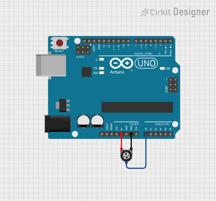
A trimpot can be used as a variable resistor to control the brightness of an LED. Below is an example circuit and code:
Circuit Connections
- Connect one terminal of the trimpot to the 5V pin on the Arduino.
- Connect the other terminal to GND.
- Connect the wiper terminal to an analog input pin (e.g., A0).
- Connect an LED to a PWM pin (e.g., D9) with a current-limiting resistor.
Arduino Code
// Define pin connections
const int trimpotPin = A0; // Analog pin connected to the trimpot wiper
const int ledPin = 9;      // PWM pin connected to the LED

void setup() {
  pinMode(ledPin, OUTPUT); // Set LED pin as output
}

void loop() {
  int sensorValue = analogRead(trimpotPin); // Read the trimpot value (0-1023)

  // Map the sensor value to a PWM range (0-255)
  int brightness = map(sensorValue, 0, 1023, 0, 255);

  analogWrite(ledPin, brightness); // Set LED brightness
}
Troubleshooting and FAQs
Common Issues and Solutions
Trimpot Not Adjusting Properly:
- Cause: The adjustment screw may be damaged or stuck.
- Solution: Check for physical damage and replace the trimpot if necessary.
Incorrect Resistance Range:
- Cause: The trimpot may not match the required resistance range for the circuit.
- Solution: Verify the resistance range and replace the trimpot with an appropriate model.
Overheating:
- Cause: The power rating of the trimpot is exceeded.
- Solution: Ensure the trimpot's power rating is suitable for the application.
No Output Voltage:
- Cause: Incorrect wiring or a damaged trimpot.
- Solution: Double-check the wiring and test the trimpot with a multimeter.
FAQs
Q: Can a trimpot be used as a permanent resistor in a circuit?
A: While trimpots are designed for calibration and fine-tuning, they can be used as permanent resistors in low-power applications. However, they are not as robust as fixed resistors for long-term use.
Q: How do I choose between a single-turn and a multi-turn trimpot?
A: Use a single-turn trimpot for quick, coarse adjustments and a multi-turn trimpot for precise, fine adjustments.
Q: Can I use a trimpot to control high currents?
A: No, trimpots are not designed to handle high currents. Use them only in low-power applications within their specified ratings.