
How to Use max30102: Examples, Pinouts, and Specs
 Design with max30102 in Cirkit Designer
Introduction
The MAX30102 is a pulse oximeter and heart-rate sensor designed for non-invasive health monitoring applications. It utilizes photoplethysmography (PPG) technology to measure blood oxygen saturation (SpO2) and heart rate. The sensor integrates red and infrared LEDs, a photodetector, optical elements, and low-noise electronics in a compact package, making it ideal for wearable devices such as fitness trackers, smartwatches, and medical monitoring systems.
Explore Projects Built with max30102
 Open Project in Cirkit Designer
 Open Project in Cirkit Designer
 Open Project in Cirkit Designer
 Open Project in Cirkit Designer
Explore Projects Built with max30102
Open Project in Cirkit DesignerOpen Project in Cirkit DesignerOpen Project in Cirkit DesignerOpen Project in Cirkit DesignerCommon Applications and Use Cases
- Wearable health monitoring devices
- Fitness trackers and smartwatches
- Medical-grade pulse oximeters
- Remote patient monitoring systems
- Research and development in biomedical applications
Technical Specifications
The MAX30102 is a highly integrated sensor with the following key specifications:
| Parameter | Value |
|---|---|
| Operating Voltage | 1.8V (core) and 3.3V (LEDs) |
| Supply Current (Typical) | 600 µA (during active measurement) |
| LED Wavelengths | Red: 660 nm, Infrared: 880 nm |
| Communication Interface | I2C (7-bit address: 0x57) |
| Sampling Rate | Programmable (up to 1000 samples per second) |
| Operating Temperature Range | -40°C to +85°C |
| Package Size | 5.6 mm x 3.3 mm x 1.55 mm |
Pin Configuration and Descriptions
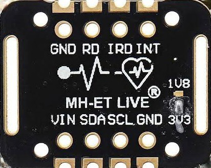
The MAX30102 has 8 pins, as described in the table below:
| Pin Name | Type | Description |
|---|---|---|
| VIN | Power | Power supply input (1.8V for core, 3.3V for LEDs) |
| GND | Ground | Ground connection |
| SDA | I/O | I2C data line |
| SCL | I/O | I2C clock line |
| INT | Output | Interrupt output (active low) |
| RD | Input | Reset pin (active low) |
| IR_DRV | Output | Infrared LED driver |
| RED_DRV | Output | Red LED driver |
Usage Instructions
How to Use the MAX30102 in a Circuit
- Power Supply: Connect the VIN pin to a 1.8V power source for the core and a 3.3V source for the LEDs. Connect the GND pin to the ground of the circuit.
- I2C Communication: Connect the SDA and SCL pins to the corresponding I2C pins of your microcontroller. Use pull-up resistors (typically 4.7 kΩ) on both lines.
- Interrupt Pin: Connect the INT pin to a GPIO pin on your microcontroller to handle interrupts.
- LED Drivers: The RED_DRV and IR_DRV pins are internally connected to the LEDs and do not require external connections.
- Reset Pin: The RD pin can be connected to a GPIO pin for manual reset or tied to the power supply for normal operation.
Important Considerations and Best Practices
- Ensure proper decoupling capacitors (e.g., 0.1 µF and 10 µF) are placed close to the VIN pin to stabilize the power supply.
- Avoid placing the sensor near strong ambient light sources to minimize interference.
- Use a low-noise power supply to ensure accurate measurements.
- Maintain proper alignment of the sensor with the skin for optimal performance.
Example Code for Arduino UNO
Below is an example of how to interface the MAX30102 with an Arduino UNO to read heart rate and SpO2 data:
#include <Wire.h>
#include "MAX30102.h" // Include the MAX30102 library

MAX30102 sensor; // Create an instance of the MAX30102 class

void setup() {
  Serial.begin(9600); // Initialize serial communication
  Wire.begin();       // Initialize I2C communication

  if (sensor.begin() == false) {
    // Check if the sensor is connected and initialized
    Serial.println("MAX30102 not detected. Please check connections.");
    while (1); // Halt execution if the sensor is not found
  }

  Serial.println("MAX30102 initialized successfully.");
}

void loop() {
  int heartRate = 0;
  int spo2 = 0;

  // Read heart rate and SpO2 values
  if (sensor.check() == true) {
    heartRate = sensor.getHeartRate(); // Get heart rate
    spo2 = sensor.getSpO2();          // Get SpO2 level

    // Print the values to the serial monitor
    Serial.print("Heart Rate: ");
    Serial.print(heartRate);
    Serial.print(" bpm, SpO2: ");
    Serial.print(spo2);
    Serial.println(" %");
  } else {
    // Handle cases where no data is available
    Serial.println("No data available. Ensure proper sensor placement.");
  }

  delay(1000); // Wait for 1 second before the next reading
}
Troubleshooting and FAQs
Common Issues and Solutions
Sensor Not Detected
- Cause: Incorrect I2C wiring or address mismatch.
- Solution: Verify the SDA and SCL connections. Ensure the I2C address (0x57) matches the library configuration.
Inaccurate Readings
- Cause: Poor sensor placement or strong ambient light interference.
- Solution: Ensure the sensor is properly aligned with the skin and shield it from ambient light.
No Data Available
- Cause: Insufficient power supply or improper initialization.
- Solution: Check the power supply voltage and ensure the sensor is initialized correctly in the code.
Interrupt Pin Not Triggering
- Cause: Interrupt pin not connected or configured.
- Solution: Verify the INT pin connection and ensure the microcontroller GPIO pin is configured as an input.
FAQs
Can the MAX30102 measure SpO2 and heart rate simultaneously?
- Yes, the MAX30102 can measure both parameters simultaneously using its dual LED and photodetector setup.
What is the maximum sampling rate of the MAX30102?
- The sensor supports a programmable sampling rate of up to 1000 samples per second.
Is the MAX30102 suitable for medical-grade applications?
- While the MAX30102 is commonly used in wearable devices, its accuracy and reliability depend on the implementation. For medical-grade applications, additional calibration and validation may be required.
Can the MAX30102 be used with a 5V microcontroller?
- Yes, but a level shifter is required for the I2C lines since the MAX30102 operates at 1.8V logic levels.