How to Use KY-037 Sound Sensor: Examples, Pinouts, and Specs
Introduction
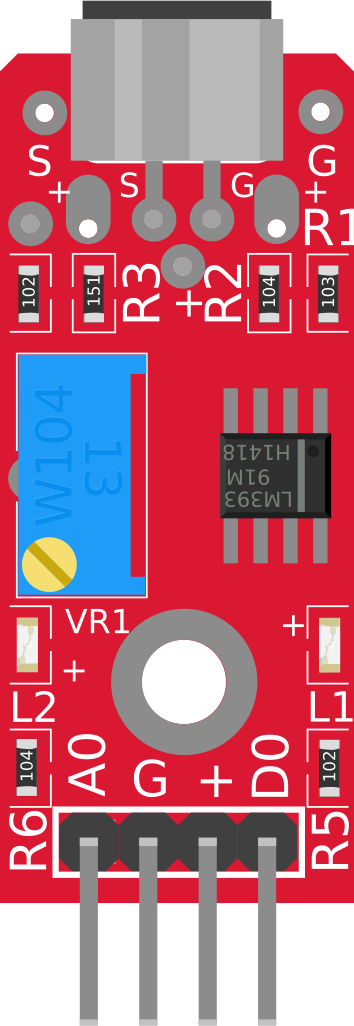
The KY-037 Sound Sensor is a device that detects sound levels and converts them into an electrical signal. It features a high-sensitivity microphone and an adjustable potentiometer to fine-tune the sensitivity. This sensor is widely used in projects requiring sound detection, such as sound-activated switches, noise level monitoring, and voice-activated systems. Its ease of use and compatibility with microcontrollers like Arduino make it a popular choice for hobbyists and professionals alike.
Explore Projects Built with KY-037 Sound Sensor
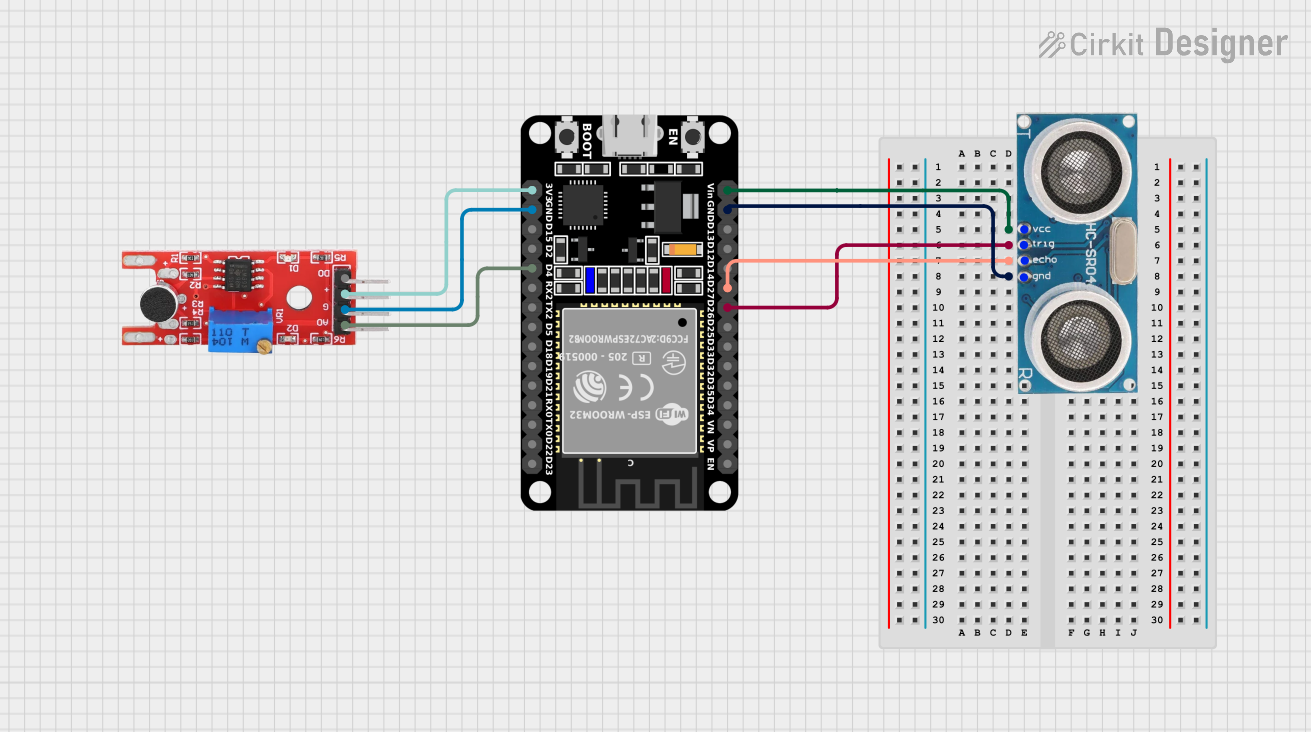
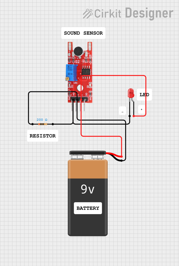
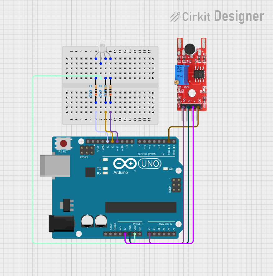
Explore Projects Built with KY-037 Sound Sensor
Technical Specifications
- Operating Voltage: 3.3V to 5V
- Output Type: Analog and Digital
- Microphone Type: High-sensitivity condenser microphone
- Adjustable Sensitivity: Via onboard potentiometer
- Dimensions: 38mm x 15mm x 13mm
Pin Configuration and Descriptions
| Pin | Name | Description |
|---|---|---|
| 1 | AO (Analog Out) | Outputs an analog signal proportional to the detected sound level. |
| 2 | DO (Digital Out) | Outputs a digital HIGH or LOW signal based on the sound threshold set by the potentiometer. |
| 3 | GND | Ground connection for the sensor. |
| 4 | VCC | Power supply input (3.3V to 5V). |
Usage Instructions
How to Use the KY-037 in a Circuit
Connect the Pins:
- Connect the VCC pin to the 5V pin of your microcontroller or power source.
- Connect the GND pin to the ground of your circuit.
- Connect the AO pin to an analog input pin of your microcontroller (e.g., A0 on Arduino) if you want to measure sound levels.
- Connect the DO pin to a digital input pin of your microcontroller (e.g., D2 on Arduino) if you want to detect sound above a certain threshold.
Adjust the Sensitivity:
- Use the onboard potentiometer to adjust the sensitivity of the digital output. Turning it clockwise increases sensitivity, while turning it counterclockwise decreases it.
Write the Code:
- Use the following example code to read both analog and digital outputs from the KY-037 sensor when connected to an Arduino UNO.
// KY-037 Sound Sensor Example Code
// This code reads the analog and digital outputs of the KY-037 sound sensor
// and prints the values to the Serial Monitor.

const int analogPin = A0; // Connect AO pin to A0 on Arduino
const int digitalPin = 2; // Connect DO pin to D2 on Arduino

void setup() {
  pinMode(digitalPin, INPUT); // Set digital pin as input
  Serial.begin(9600);         // Initialize serial communication at 9600 baud
}

void loop() {
  int analogValue = analogRead(analogPin); // Read analog value from AO pin
  int digitalValue = digitalRead(digitalPin); // Read digital value from DO pin

  // Print the values to the Serial Monitor
  Serial.print("Analog Value: ");
  Serial.print(analogValue);
  Serial.print(" | Digital Value: ");
  Serial.println(digitalValue);

  delay(500); // Wait for 500ms before the next reading
}
Important Considerations and Best Practices
- Power Supply: Ensure the sensor is powered within its operating voltage range (3.3V to 5V). Exceeding this range may damage the sensor.
- Noise Interference: Place the sensor away from sources of electrical noise or vibrations to avoid false readings.
- Sensitivity Adjustment: Fine-tune the potentiometer to achieve the desired sensitivity for your application.
- Analog vs. Digital Output: Use the analog output for precise sound level measurements and the digital output for simple sound detection.
Troubleshooting and FAQs
Common Issues and Solutions
No Output from the Sensor:
- Check the wiring to ensure all connections are secure and correct.
- Verify that the power supply voltage is within the specified range (3.3V to 5V).
Digital Output Always HIGH or LOW:
- Adjust the potentiometer to change the sensitivity threshold.
- Ensure the sound level in the environment is within the sensor's detection range.
Inconsistent Readings:
- Avoid placing the sensor near strong electromagnetic interference or vibrations.
- Use a stable power supply to prevent voltage fluctuations.
Analog Output Not Changing:
- Verify that the microphone is functional and not physically damaged.
- Check the analog input pin configuration in your microcontroller code.
FAQs
Q: Can the KY-037 detect specific frequencies of sound?
A: No, the KY-037 is designed to detect general sound levels and cannot differentiate between specific frequencies.
Q: How far can the KY-037 detect sound?
A: The detection range depends on the sound intensity and the sensitivity setting. It is best suited for detecting sounds within a few meters.
Q: Can I use the KY-037 with a 3.3V microcontroller like ESP32?
A: Yes, the KY-037 operates at 3.3V to 5V, making it compatible with 3.3V microcontrollers like the ESP32.
Q: Is the KY-037 suitable for outdoor use?
A: The KY-037 is not weatherproof and should be used in indoor environments or protected from moisture and extreme temperatures.
By following this documentation, you can effectively integrate the KY-037 Sound Sensor into your projects and troubleshoot common issues.