Cirkit Designer Logo
Cirkit Designer
Your all-in-one circuit design IDE
Home / 
Component Documentation

How to Use Lampu Led 5v: Examples, Pinouts, and Specs

Image of Lampu Led 5v
Cirkit Designer LogoDesign with Lampu Led 5v in Cirkit Designer

Introduction

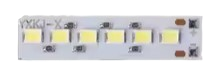
The Lampu LED 5V is a light-emitting diode (LED) designed to operate at a 5V input. Manufactured by Arduino (Part ID: UNO), this LED lamp is a versatile and energy-efficient component that emits light when an electric current flows through it. It is commonly used in low-voltage applications such as status indicators, decorative lighting, and DIY electronics projects.

Explore Projects Built with Lampu Led 5v

Use Cirkit Designer to design, explore, and prototype these projects online. Some projects support real-time simulation. Click "Open Project" to start designing instantly!
12V to 5V Power Supply with LED Indicator and Push Switch
Image of Power Supply LVCO: A project utilizing Lampu Led 5v in a practical application
This circuit is a 12V to 5V regulated power supply with an LED indicator. It uses a 5408 diode for reverse polarity protection, an LM340T5 7805 voltage regulator to step down the voltage to 5V, and a push switch to control the LED indicator. The circuit also includes capacitors for filtering and a resistor to limit the current through the LED.
Cirkit Designer LogoOpen Project in Cirkit Designer
LED Array with Push Switch Control and Voltage Regulation
Image of Transformer safty device complete: A project utilizing Lampu Led 5v in a practical application
This circuit is a power supply and control system that steps down 220V AC to 24V AC using a transformer, rectifies it to DC using a bridge rectifier, and regulates it to 5V DC. It includes multiple LEDs controlled by push switches and a relay, with a capacitor for smoothing the output.
Cirkit Designer LogoOpen Project in Cirkit Designer
Light-Activated Relay with LED Indicator
Image of Street Light: A project utilizing Lampu Led 5v in a practical application
This circuit uses a photocell (LDR) to control a 5V relay, which in turn controls the power to a red LED. The relay is powered by a USB plug, and a resistor is used to limit the current to the LED.
Cirkit Designer LogoOpen Project in Cirkit Designer
Raspberry Pi Controlled LED Indicator with Pushbutton Interface
Image of praca2: A project utilizing Lampu Led 5v in a practical application
This circuit is a simple LED control system using a Raspberry Pi 5. It includes three LEDs (red, blue, and yellow) each connected in series with a 100k Ohm resistor, and a pushbutton for user input. The Raspberry Pi controls the LEDs through its GPIO pins and is powered via a USB Type-C power supply, with additional peripherals like a monitor and microphone connected.
Cirkit Designer LogoOpen Project in Cirkit Designer

Explore Projects Built with Lampu Led 5v

Use Cirkit Designer to design, explore, and prototype these projects online. Some projects support real-time simulation. Click "Open Project" to start designing instantly!
Image of Power Supply LVCO: A project utilizing Lampu Led 5v in a practical application
12V to 5V Power Supply with LED Indicator and Push Switch
This circuit is a 12V to 5V regulated power supply with an LED indicator. It uses a 5408 diode for reverse polarity protection, an LM340T5 7805 voltage regulator to step down the voltage to 5V, and a push switch to control the LED indicator. The circuit also includes capacitors for filtering and a resistor to limit the current through the LED.
Cirkit Designer LogoOpen Project in Cirkit Designer
Image of Transformer safty device complete: A project utilizing Lampu Led 5v in a practical application
LED Array with Push Switch Control and Voltage Regulation
This circuit is a power supply and control system that steps down 220V AC to 24V AC using a transformer, rectifies it to DC using a bridge rectifier, and regulates it to 5V DC. It includes multiple LEDs controlled by push switches and a relay, with a capacitor for smoothing the output.
Cirkit Designer LogoOpen Project in Cirkit Designer
Image of Street Light: A project utilizing Lampu Led 5v in a practical application
Light-Activated Relay with LED Indicator
This circuit uses a photocell (LDR) to control a 5V relay, which in turn controls the power to a red LED. The relay is powered by a USB plug, and a resistor is used to limit the current to the LED.
Cirkit Designer LogoOpen Project in Cirkit Designer
Image of praca2: A project utilizing Lampu Led 5v in a practical application
Raspberry Pi Controlled LED Indicator with Pushbutton Interface
This circuit is a simple LED control system using a Raspberry Pi 5. It includes three LEDs (red, blue, and yellow) each connected in series with a 100k Ohm resistor, and a pushbutton for user input. The Raspberry Pi controls the LEDs through its GPIO pins and is powered via a USB Type-C power supply, with additional peripherals like a monitor and microphone connected.
Cirkit Designer LogoOpen Project in Cirkit Designer

Common Applications:

  • Power and status indicators in electronic devices
  • Decorative and ambient lighting
  • DIY electronics and prototyping
  • Educational projects for learning about LEDs and circuits

Technical Specifications

Below are the key technical details for the Lampu LED 5V:

Parameter Value
Operating Voltage 5V DC
Forward Current (If) 20mA (typical)
Power Consumption 0.1W
Luminous Intensity 1000-1500 mcd (typical)
Viewing Angle 20°-30°
Color Varies (e.g., red, green, blue)
Polarity Anode (+), Cathode (-)

Pin Configuration:

The Lampu LED 5V has two pins:

Pin Description
Anode (+) Connects to the positive terminal of the power supply or circuit.
Cathode (-) Connects to the negative terminal (ground).

Usage Instructions

How to Use the Lampu LED 5V in a Circuit:

  1. Identify the Pins: The longer leg of the LED is the anode (+), and the shorter leg is the cathode (-). If the legs are trimmed, look for a flat edge on the LED body, which indicates the cathode.
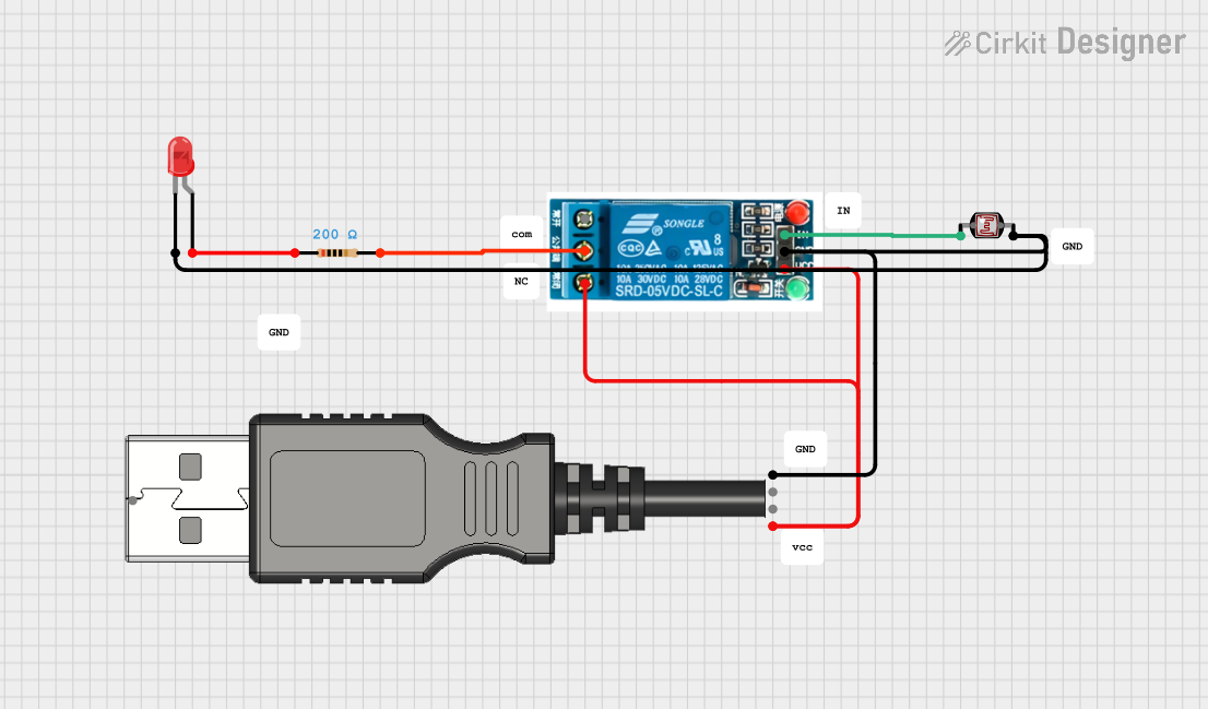
  2. Connect a Resistor: To prevent damage, always use a current-limiting resistor in series with the LED. For a 5V supply, a 220Ω resistor is commonly used.
  3. Power the LED: Connect the anode to the positive terminal of the power supply and the cathode to the ground. The LED will emit light when powered.

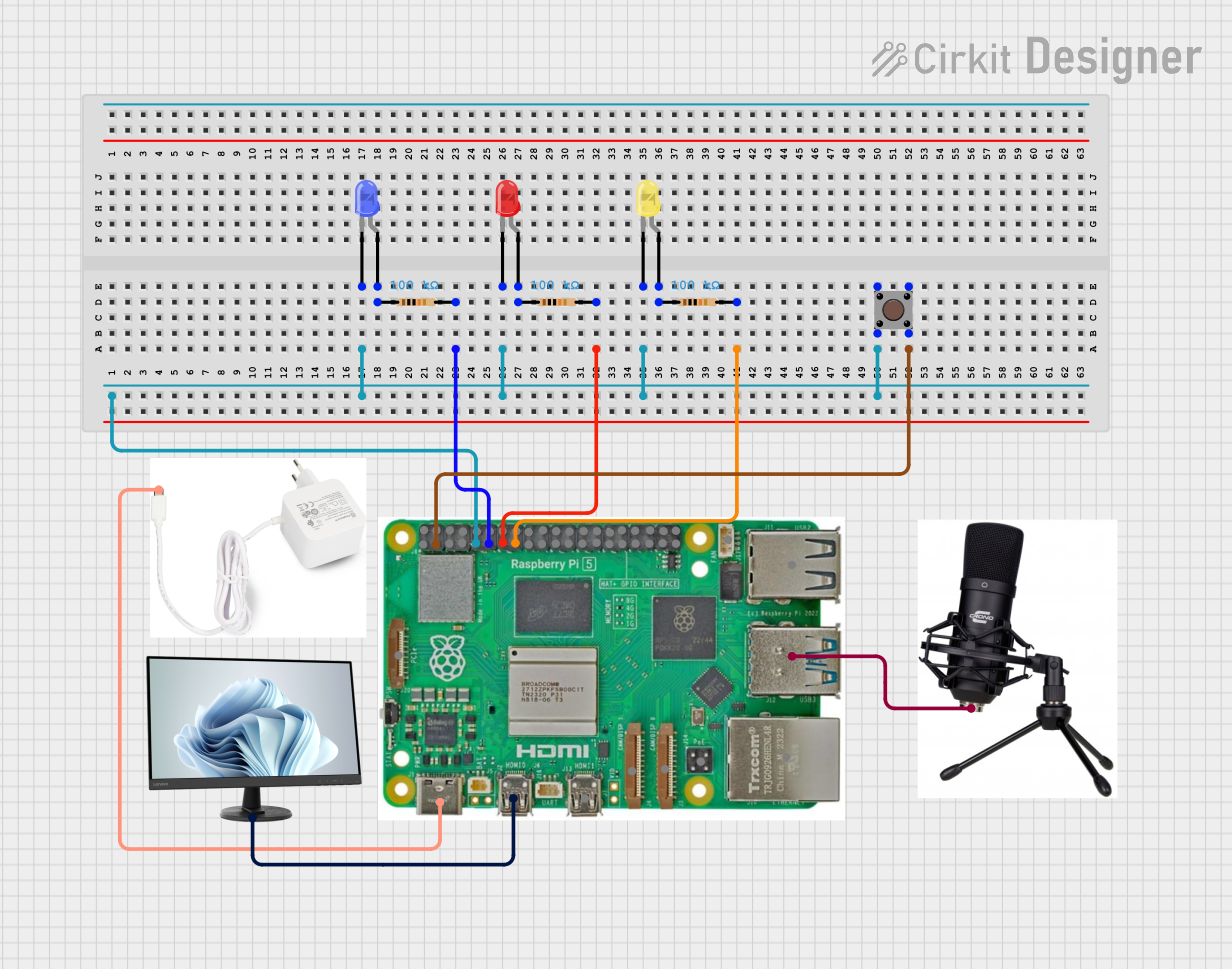
Example Circuit with Arduino UNO:

The Lampu LED 5V can be easily connected to an Arduino UNO for control. Below is an example of how to blink the LED using Arduino code:

Circuit Diagram:

  • Connect the anode (+) of the LED to digital pin 13 on the Arduino UNO through a 220Ω resistor.
  • Connect the cathode (-) of the LED to the GND pin on the Arduino UNO.

Arduino Code:

// Lampu LED 5V Blink Example
// This code blinks the LED connected to pin 13 on the Arduino UNO.

void setup() {
  pinMode(13, OUTPUT); // Set pin 13 as an output pin
}

void loop() {
  digitalWrite(13, HIGH); // Turn the LED on
  delay(1000);            // Wait for 1 second
  digitalWrite(13, LOW);  // Turn the LED off
  delay(1000);            // Wait for 1 second
}

Important Considerations:

  • Resistor Selection: Always use a resistor to limit the current through the LED. Failure to do so may damage the LED.
  • Polarity: Ensure correct polarity when connecting the LED. Reversing the connections may prevent the LED from lighting up or cause damage.
  • Power Supply: Use a stable 5V DC power source to avoid fluctuations that could harm the LED.

Troubleshooting and FAQs

Common Issues:

  1. The LED Does Not Light Up:

    • Cause: Incorrect polarity.
    • Solution: Verify that the anode is connected to the positive terminal and the cathode to the ground.
  2. The LED is Dim:

    • Cause: Resistor value too high.
    • Solution: Use a lower resistance value (e.g., 220Ω) to increase brightness.
  3. The LED Burns Out:

    • Cause: No current-limiting resistor or excessive voltage.
    • Solution: Always use a resistor and ensure the supply voltage does not exceed 5V.
  4. Flickering LED:

    • Cause: Unstable power supply or loose connections.
    • Solution: Check the power source and ensure all connections are secure.

FAQs:

  • Q: Can I use the Lampu LED 5V with a 3.3V power supply?
    A: Yes, but the brightness will be reduced. Ensure the resistor value is adjusted accordingly.

  • Q: What happens if I connect the LED without a resistor?
    A: The LED may draw excessive current, leading to overheating and permanent damage.

  • Q: Can I use multiple Lampu LED 5V in a single circuit?
    A: Yes, but each LED should have its own current-limiting resistor, or they should be connected in parallel with a shared resistor calculated for the total current.

This concludes the documentation for the Lampu LED 5V. Follow the guidelines above to ensure safe and effective use of this component in your projects!