How to Use G2 High-Power Motor Driver 18v25: Examples, Pinouts, and Specs
Introduction
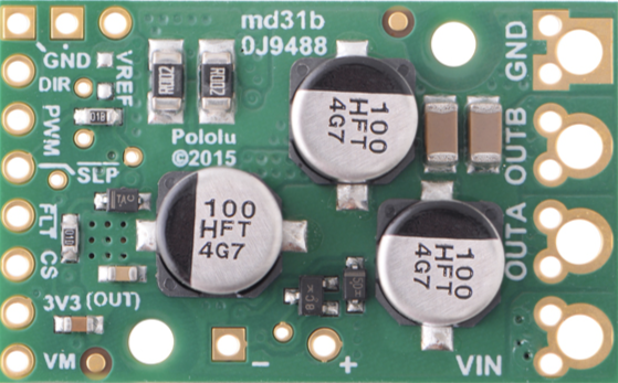
The G2 High-Power Motor Driver 18v25 (Manufacturer Part ID: 2994) by Pololu is a robust and efficient motor driver designed to control high-power DC motors. It supports a voltage rating of up to 18V and can handle continuous currents of up to 25A, making it ideal for demanding applications such as robotics, industrial automation, and electric vehicles. Its compact design, high efficiency, and built-in protection features make it a reliable choice for controlling powerful motors.
Explore Projects Built with G2 High-Power Motor Driver 18v25


Explore Projects Built with G2 High-Power Motor Driver 18v25
Common Applications
- Robotics (e.g., motorized arms, mobile robots)
- Industrial automation systems
- Electric vehicles and carts
- Conveyor belts and other high-power motorized systems
- Remote-controlled vehicles and drones
Technical Specifications
The following table outlines the key technical details of the G2 High-Power Motor Driver 18v25:
| Parameter | Value |
|---|---|
| Operating Voltage Range | 6.5V to 30V |
| Continuous Current Rating | 25A |
| Peak Current Rating | 50A (for short durations) |
| Control Interface | PWM, DIR (direction), and GND |
| Logic Voltage Range | 2.5V to 5.5V |
| PWM Frequency Range | Up to 100 kHz |
| Reverse Voltage Protection | Yes |
| Overcurrent Protection | Yes |
| Overtemperature Shutdown | Yes |
| Dimensions | 1.3" × 0.8" × 0.5" (33 × 20 × 13 mm) |
| Weight | 5.5 g |
Pin Configuration and Descriptions
The G2 High-Power Motor Driver 18v25 has the following pin layout:
| Pin Name | Type | Description |
|---|---|---|
| VIN | Power Input | Motor power supply input (6.5V to 30V). |
| GND | Power Ground | Ground connection for the motor power supply and logic. |
| OUTA | Motor Output | Motor output terminal A. |
| OUTB | Motor Output | Motor output terminal B. |
| PWM | Logic Input | Pulse-width modulation input for speed control. |
| DIR | Logic Input | Direction control input. |
| SLP | Logic Input | Sleep mode input (active low). Pull high to enable the driver. |
| FLT | Logic Output | Fault indicator output (active low). Indicates overcurrent or overtemperature. |
Usage Instructions
How to Use the Component in a Circuit
- Power Supply: Connect a DC power supply (6.5V to 30V) to the
VINandGNDpins. Ensure the power supply can provide sufficient current for your motor. - Motor Connection: Connect the motor terminals to the
OUTAandOUTBpins. - Logic Inputs:
- Connect the
PWMpin to a PWM signal source (e.g., a microcontroller or Arduino) to control motor speed. - Use the
DIRpin to set the motor's direction (logic high for one direction, logic low for the other). - Pull the
SLPpin high to enable the driver. Pull it low to put the driver into sleep mode.
- Connect the
- Fault Monitoring: Optionally, connect the
FLTpin to a microcontroller input to monitor fault conditions.
Important Considerations and Best Practices
- Heat Dissipation: The driver can handle high currents, but proper heat dissipation is essential. Use a heatsink or ensure adequate airflow if operating near the maximum current rating.
- Current Limiting: Ensure the motor's stall current does not exceed the driver's peak current rating (50A).
- PWM Frequency: Use a PWM frequency within the recommended range (up to 100 kHz) for optimal performance.
- Logic Voltage Compatibility: Ensure the logic voltage levels (2.5V to 5.5V) are compatible with your microcontroller.
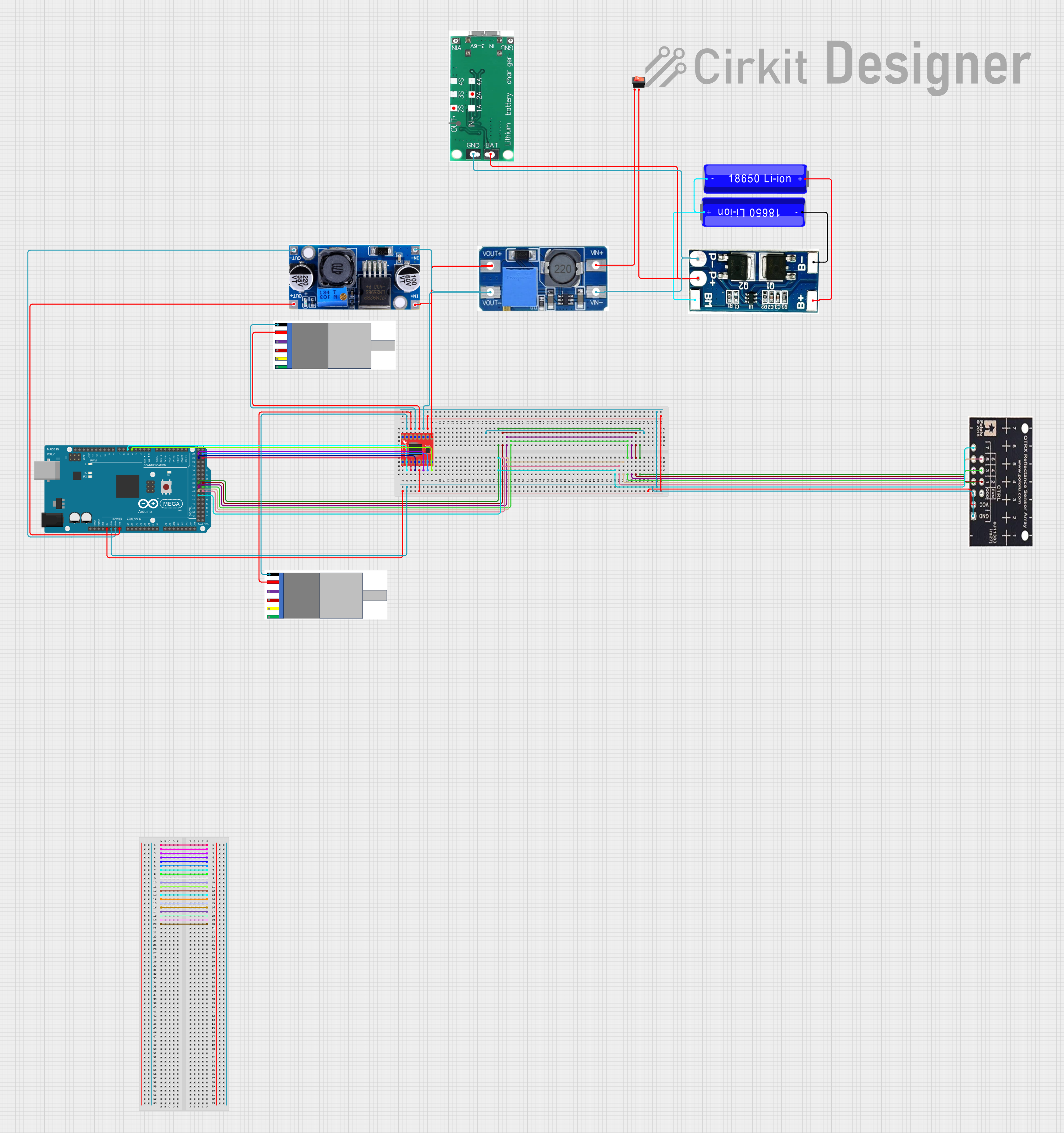
Example: Connecting to an Arduino UNO
Below is an example of how to control the G2 High-Power Motor Driver 18v25 using an Arduino UNO:
Circuit Connections
- Connect
VINandGNDto a 12V power supply. - Connect the motor terminals to
OUTAandOUTB. - Connect the
PWMpin to Arduino pin 9. - Connect the
DIRpin to Arduino pin 8. - Connect the
SLPpin to Arduino pin 7. - Connect the
FLTpin to Arduino pin 6 (optional, for fault monitoring).
Arduino Code
// Define pin connections
const int pwmPin = 9;  // PWM pin for speed control
const int dirPin = 8;  // Direction control pin
const int slpPin = 7;  // Sleep mode pin
const int fltPin = 6;  // Fault indicator pin (optional)

void setup() {
  // Set pin modes
  pinMode(pwmPin, OUTPUT);
  pinMode(dirPin, OUTPUT);
  pinMode(slpPin, OUTPUT);
  pinMode(fltPin, INPUT);

  // Enable the motor driver
  digitalWrite(slpPin, HIGH);
}

void loop() {
  // Set motor direction (HIGH for forward, LOW for reverse)
  digitalWrite(dirPin, HIGH);

  // Set motor speed using PWM (0 to 255)
  analogWrite(pwmPin, 128);  // 50% duty cycle

  // Optional: Check for faults
  if (digitalRead(fltPin) == LOW) {
    // Fault detected, take appropriate action
    digitalWrite(slpPin, LOW);  // Disable the driver
    while (1);  // Halt the program
  }

  delay(1000);  // Run the motor for 1 second

  // Stop the motor
  analogWrite(pwmPin, 0);
  delay(1000);  // Wait for 1 second
}
Troubleshooting and FAQs
Common Issues and Solutions
Motor Does Not Run
Cause: The
SLPpin is not pulled high.Solution: Ensure the
SLPpin is connected to a logic high signal.Cause: Insufficient power supply.
Solution: Verify that the power supply voltage and current meet the motor's requirements.
Driver Overheats
- Cause: Excessive current draw or poor heat dissipation.
- Solution: Use a heatsink or improve airflow around the driver.
Fault Indicator (FLT) is Active
- Cause: Overcurrent or overtemperature condition.
- Solution: Check the motor's current draw and ensure it is within the driver's limits. Allow the driver to cool down before restarting.
PWM Signal Not Detected
- Cause: Incorrect PWM frequency or signal level.
- Solution: Verify the PWM signal is within the recommended frequency range and logic voltage levels.
FAQs
Can I use this driver with a 24V motor? Yes, as long as the motor's operating voltage is within the 6.5V to 30V range and its current draw does not exceed 25A continuously.
What happens if the motor stalls? If the motor's stall current exceeds the driver's peak current rating (50A), the driver will trigger overcurrent protection and shut down to prevent damage.
Is reverse polarity protection included? Yes, the driver includes reverse voltage protection to safeguard against incorrect power supply connections.