How to Use Single phase Energy Meter: Examples, Pinouts, and Specs
Introduction
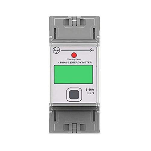
The Single Phase Energy Meter, model EM-11XX4, manufactured by L&T, is an electronic device designed to measure the amount of electrical energy consumed by a load in a single-phase electrical circuit. This meter is commonly used in residential and commercial settings to track electricity usage for billing purposes. It is known for its accuracy, reliability, and ease of integration into existing electrical systems.
Explore Projects Built with Single phase Energy Meter
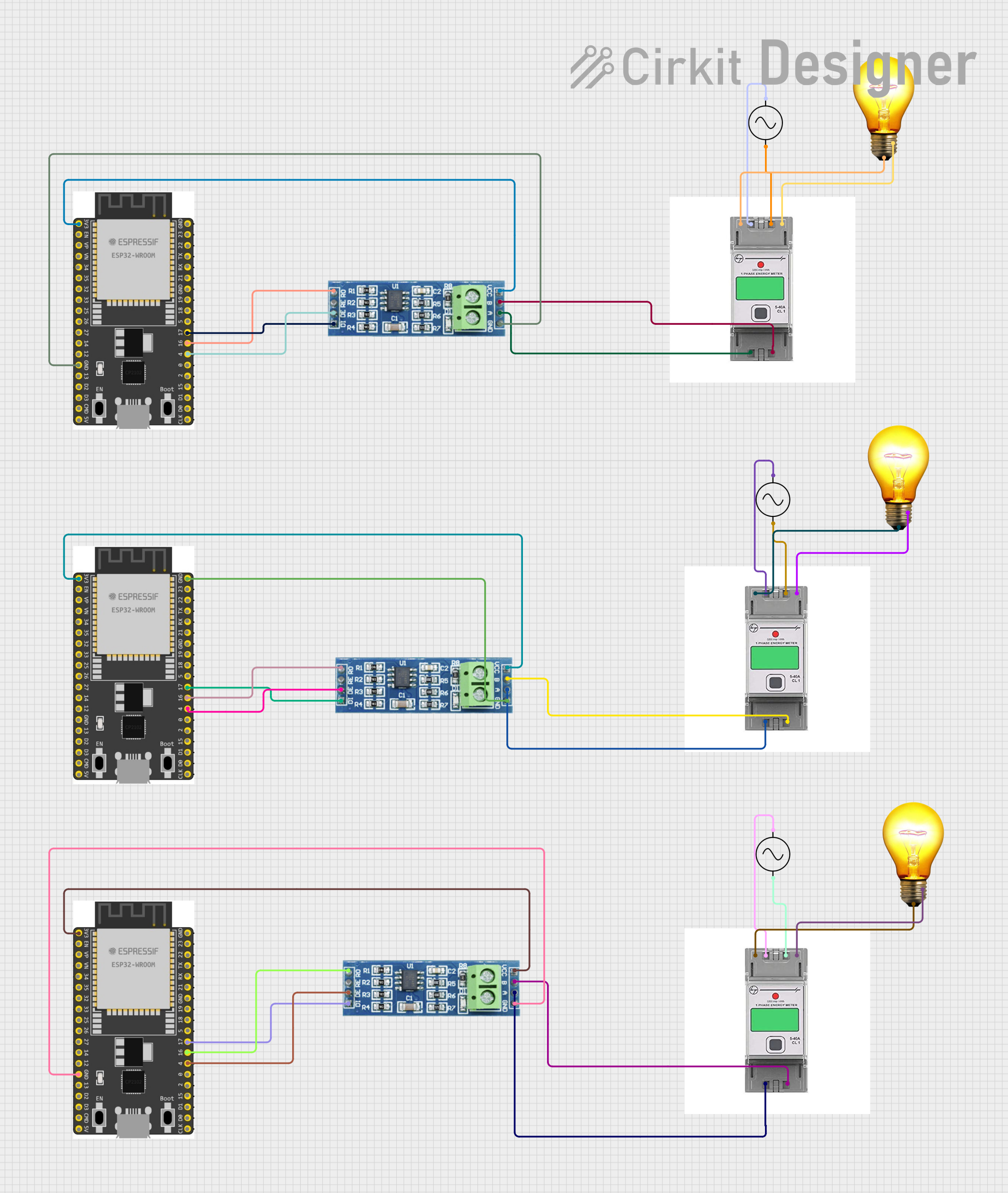
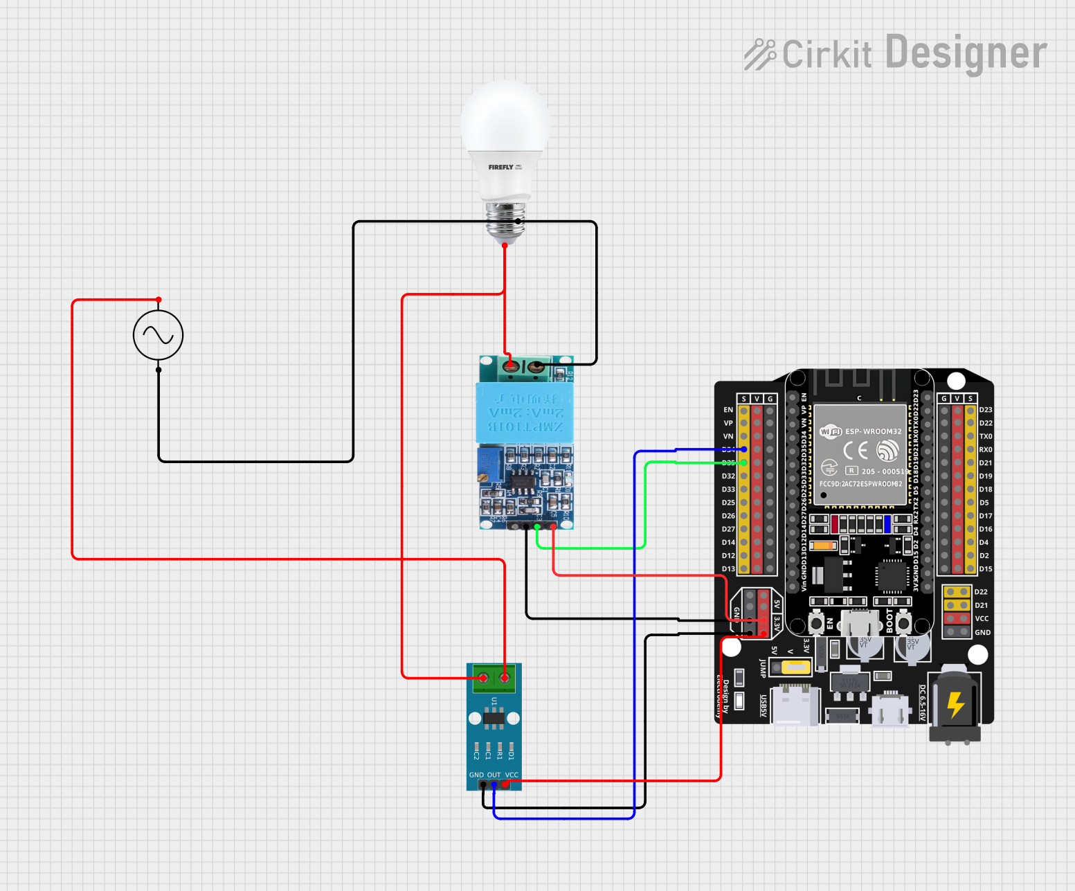
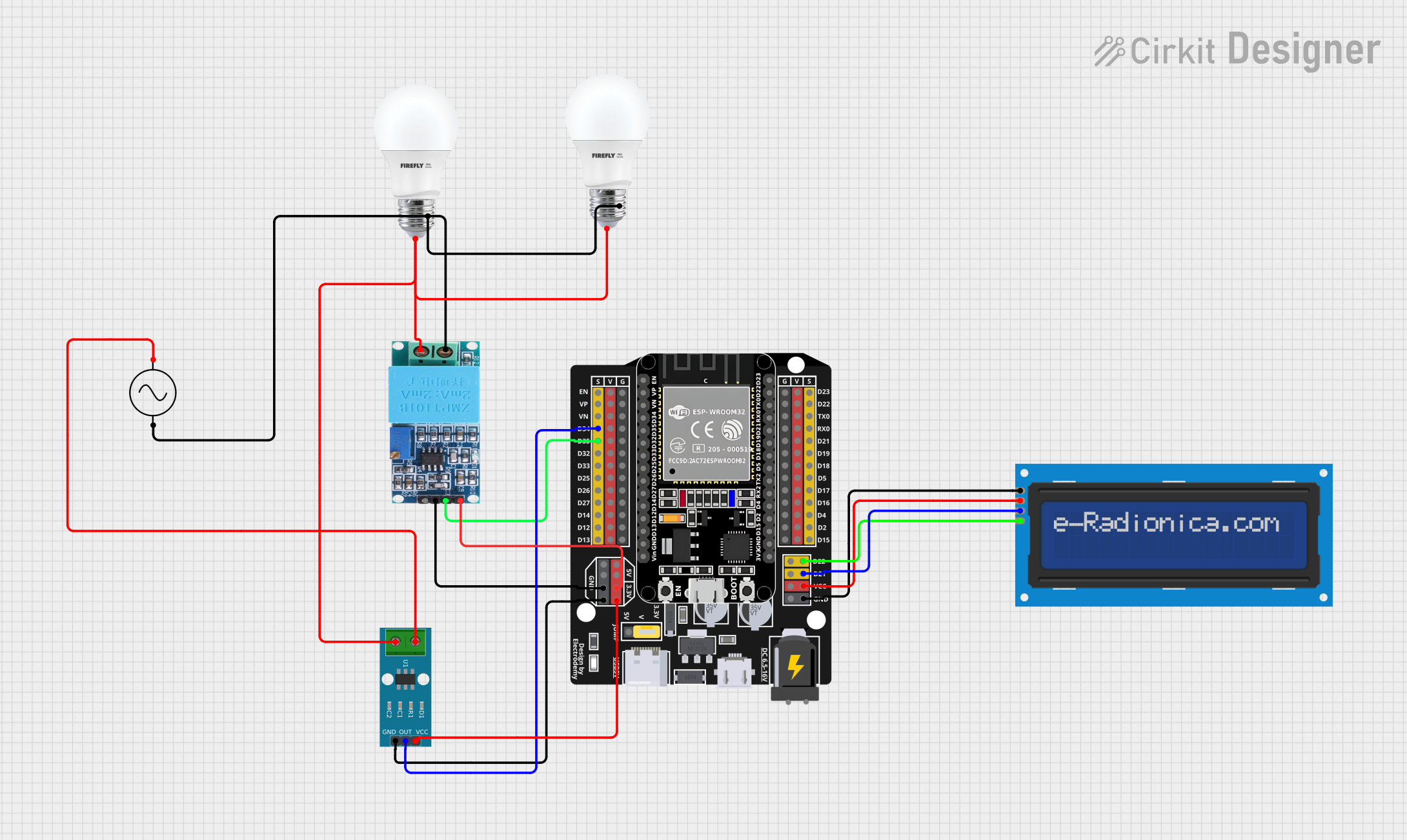
Explore Projects Built with Single phase Energy Meter
Common Applications and Use Cases
- Residential electricity consumption measurement
- Commercial energy management
- Energy sub-metering in apartments and office buildings
- Monitoring energy usage for specific circuits or equipment
Technical Specifications
Key Technical Details
- Voltage Rating: 230V AC (typical for single-phase connections)
- Current Rating: Can vary (e.g., 5-30A)
- Frequency: 50Hz or 60Hz
- Accuracy Class: As per manufacturer's specification (e.g., Class 1.0)
- Operating Temperature Range: -10°C to 55°C
- Display: LCD/LED for energy consumption readout
Pin Configuration and Descriptions
| Pin Number | Description | Notes |
|---|---|---|
| 1 | Phase Input | Connect to the live wire |
| 2 | Neutral Input | Connect to the neutral wire |
| 3 | Load Output (Phase) | Connect to the load's live input |
| 4 | Load Output (Neutral) | Connect to the load's neutral |
| 5 | Pulse Output (Optional) | For external monitoring |
| 6 | Communication Port (Optional) | RS-485/Infrared for data logging |
Note: The actual pin configuration may vary based on the specific model of the EM-11XX4. Refer to the manufacturer's datasheet for exact details.
Usage Instructions
How to Use the Component in a Circuit
- Installation: The energy meter should be installed by a qualified electrician, ensuring that it is placed in series with the load.
- Wiring: Connect the phase and neutral inputs to the corresponding supply lines. The load should be connected to the load output terminals.
- Configuration: Set up the meter according to the manufacturer's instructions, which may involve setting the tariff rate, date, and time.
- Operation: Once installed and configured, the meter will automatically begin measuring energy consumption.
Important Considerations and Best Practices
- Ensure that the meter's current and voltage ratings match the specifications of the electrical circuit.
- Avoid exposing the meter to extreme temperatures, moisture, or dust.
- Regular calibration may be required to maintain accuracy over time.
- For safety, always disconnect power before performing any maintenance on the meter.
Troubleshooting and FAQs
Common Issues Users Might Face
- Display Not Working: Check the power supply to the meter and verify wiring connections.
- Inaccurate Readings: Ensure the meter is calibrated and that there are no external magnetic fields interfering with the operation.
- No Pulse Output: Verify that the pulse output feature is enabled and correctly configured.
Solutions and Tips for Troubleshooting
- If the meter is not functioning, first check the fuse and circuit breaker connected to the meter.
- For communication issues, ensure that the communication port is properly configured and that compatible software is used for data logging.
- Regularly check and tighten the terminal connections to prevent energy loss and potential safety hazards.
FAQs
Q: Can the EM-11XX4 meter be used with solar panels? A: Yes, as long as the solar inverter output is single-phase and within the meter's voltage and current ratings.
Q: How can I monitor my energy usage remotely? A: If your meter has a communication port, you can connect it to a compatible data logger or monitoring system.
Q: What should I do if the meter shows an error code? A: Refer to the manufacturer's manual for the specific error code description and follow the recommended troubleshooting steps.
Note: For any specific issues not covered in this documentation, please contact L&T customer support for assistance.
Code Example for Arduino UNO Integration
// This example assumes the use of a digital pulse output from the EM-11XX4 meter.
// The pulse output is connected to a digital input pin on the Arduino UNO.

const int pulsePin = 2; // Digital pin connected to the pulse output of the meter
volatile unsigned long pulseCount = 0;

void setup() {
  Serial.begin(9600);
  pinMode(pulsePin, INPUT_PULLUP);
  attachInterrupt(digitalPinToInterrupt(pulsePin), onPulse, FALLING);
}

void loop() {
  // Assuming 1000 pulses/kWh, which is a common pulse constant for energy meters.
  // Check your meter's specifications for the correct value.
  const float pulseConstant = 1000.0; // Pulses per kWh
  float energyConsumed = pulseCount / pulseConstant; // Calculate energy in kWh

  Serial.print("Energy Consumed: ");
  Serial.print(energyConsumed);
  Serial.println(" kWh");

  // Add a delay or other functionality as needed.
  delay(1000);
}

void onPulse() {
  // Increment the pulse count when an interrupt is detected
  pulseCount++;
}
Note: The above code is a simple example to demonstrate how to count pulses from the energy meter using an Arduino UNO. The actual implementation may vary based on the specific requirements of your project. Always refer to the energy meter's datasheet for accurate pulse output specifications.