
How to Use 7-Segment Panel Voltmeter: Examples, Pinouts, and Specs
 Design with 7-Segment Panel Voltmeter in Cirkit Designer
Introduction
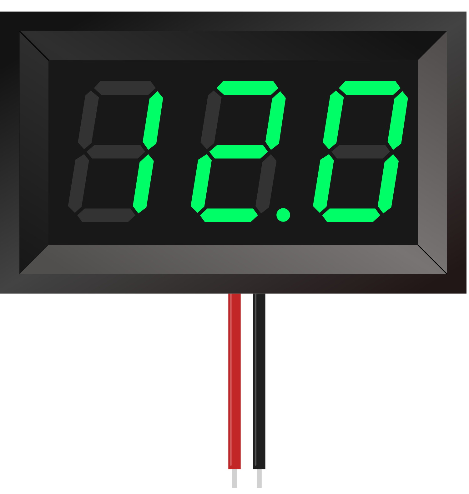
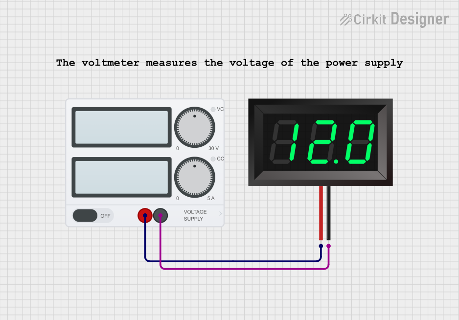
A 7-segment panel voltmeter is an electronic device used to measure and display voltage levels in a circuit. It features a digital display made up of seven segments that illuminate to represent numerical values, providing a clear and easy-to-read output of the measured voltage. These devices are compact, reliable, and widely used in various applications.
Explore Projects Built with 7-Segment Panel Voltmeter
 Open Project in Cirkit Designer
 Open Project in Cirkit Designer
 Open Project in Cirkit Designer
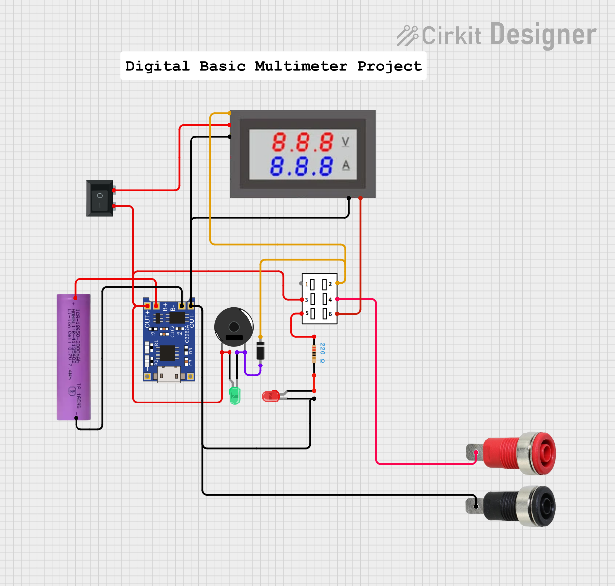 Open Project in Cirkit Designer
Explore Projects Built with 7-Segment Panel Voltmeter
Open Project in Cirkit DesignerOpen Project in Cirkit DesignerOpen Project in Cirkit DesignerOpen Project in Cirkit DesignerCommon Applications and Use Cases
- Monitoring voltage levels in power supplies
- Battery voltage measurement
- DIY electronics projects
- Industrial equipment and control panels
- Automotive voltage monitoring
Technical Specifications
Below are the key technical details for a typical 7-segment panel voltmeter. Specifications may vary depending on the specific model.
General Specifications
- Input Voltage Range: 0V to 100V DC (common range; varies by model)
- Operating Voltage: 4.5V to 30V DC (for powering the module)
- Display Type: 7-segment LED
- Display Color: Red, Green, Blue (varies by model)
- Accuracy: ±1% (typical)
- Refresh Rate: ~200ms
- Power Consumption: <20mA
- Operating Temperature: -10°C to 60°C
Pin Configuration and Descriptions
The 7-segment panel voltmeter typically has three or four pins for connections. Below is a table describing the pin configuration:
| Pin | Label | Description |
|---|---|---|
| 1 | VCC | Power supply input (4.5V to 30V DC). Provides power to the voltmeter module. |
| 2 | GND | Ground connection. Common ground for power and measurement. |
| 3 | VIN | Voltage input to be measured. Connect this pin to the voltage source. |
| 4* | NC or ADJ | Optional pin for calibration or adjustment (varies by model; may not be present). |
* Note: Some models may not include the fourth pin.
Usage Instructions
How to Use the Component in a Circuit
- Power the Module: Connect the
VCCpin to a DC power source (4.5V to 30V) and theGNDpin to the ground of the power source. - Connect the Voltage Source: Attach the
VINpin to the voltage source you want to measure. Ensure the voltage does not exceed the module's input range (e.g., 0V to 100V DC). - Optional Calibration: If your module includes an adjustment pin (
ADJ), use a small screwdriver to fine-tune the reading for improved accuracy.
Important Considerations and Best Practices
- Voltage Range: Ensure the input voltage to be measured does not exceed the specified range of the module. Overvoltage can damage the device.
- Power Supply: Use a stable DC power source to avoid fluctuations in the display reading.
- Common Ground: Ensure the ground of the power supply and the voltage source being measured are connected to the same ground (
GNDpin). - Isolation: For high-voltage measurements, consider using an isolation circuit to protect the voltmeter and other components.
- Mounting: Secure the panel voltmeter in a suitable enclosure or panel cutout to protect it from physical damage.
Example: Connecting to an Arduino UNO
The 7-segment panel voltmeter is typically standalone, but you can use an Arduino UNO to measure voltage and display it on the voltmeter. Below is an example:
Circuit Connections
- Connect the
VCCpin of the voltmeter to the Arduino's 5V pin. - Connect the
GNDpin of the voltmeter to the Arduino's GND pin. - Connect the
VINpin of the voltmeter to the voltage source you want to measure.
Arduino Code Example
// Example code to measure voltage using Arduino and display it on a 7-segment panel voltmeter
const int voltagePin = A0; // Analog pin to read voltage
float voltage = 0.0;       // Variable to store measured voltage

void setup() {
  Serial.begin(9600); // Initialize serial communication for debugging
}

void loop() {
  int sensorValue = analogRead(voltagePin); // Read analog input
  voltage = sensorValue * (5.0 / 1023.0);   // Convert to voltage (assuming 5V reference)

  // Print voltage to Serial Monitor
  Serial.print("Measured Voltage: ");
  Serial.print(voltage);
  Serial.println(" V");

  delay(500); // Delay for stability
}
Note: The Arduino code is for measuring voltage using the Arduino's ADC. The 7-segment panel voltmeter will display the voltage directly when connected to a voltage source.
Troubleshooting and FAQs
Common Issues and Solutions
No Display or Flickering Display
- Cause: Insufficient or unstable power supply.
- Solution: Ensure the
VCCpin is connected to a stable DC power source within the specified range.
Incorrect Voltage Reading
- Cause: Calibration issue or incorrect wiring.
- Solution: Use the adjustment pin (
ADJ) to calibrate the reading. Double-check all connections.
Overvoltage Damage
- Cause: Input voltage exceeds the specified range.
- Solution: Always verify the voltage source before connecting it to the
VINpin. Use a voltage divider for high-voltage sources.
Display Not Turning On
- Cause: Incorrect polarity or loose connections.
- Solution: Verify the polarity of the power supply and ensure all connections are secure.
FAQs
Q1: Can I use the 7-segment panel voltmeter to measure AC voltage?
A1: No, this device is designed for DC voltage measurement only. For AC voltage, use an appropriate AC voltmeter.
Q2: How do I calibrate the voltmeter?
A2: If your model includes an adjustment pin (ADJ), use a small screwdriver to turn the potentiometer until the displayed value matches a known reference voltage.
Q3: Can I measure voltages higher than 100V?
A3: No, exceeding the maximum input voltage can damage the device. Use a voltage divider circuit to step down higher voltages before measurement.
Q4: What happens if I reverse the polarity of the input voltage?
A4: Most models include reverse polarity protection, but it is best to avoid reversing the polarity to prevent potential damage.
By following this documentation, you can effectively use and troubleshoot a 7-segment panel voltmeter in your projects.