How to Use Mini Maestro 12-Channel USB Servo Controller: Examples, Pinouts, and Specs
Introduction
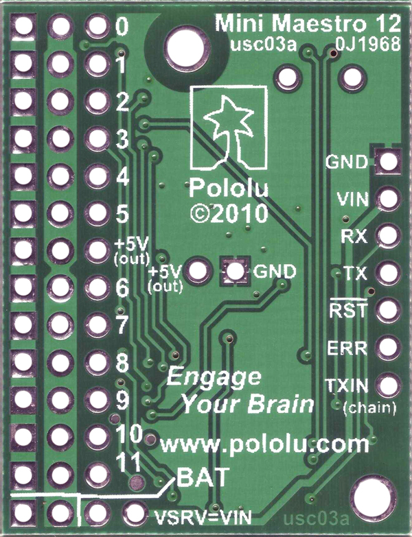
The Mini Maestro 12-Channel USB Servo Controller by Pololu is a versatile and compact device designed for precise control of up to 12 servos. It offers advanced features such as configurable speed and acceleration settings, internal scripting capabilities, and multiple control interfaces, including USB, TTL serial, and hobby radio control (RC). This makes it an ideal choice for robotics, animatronics, and other applications requiring precise servo control.
Explore Projects Built with Mini Maestro 12-Channel USB Servo Controller
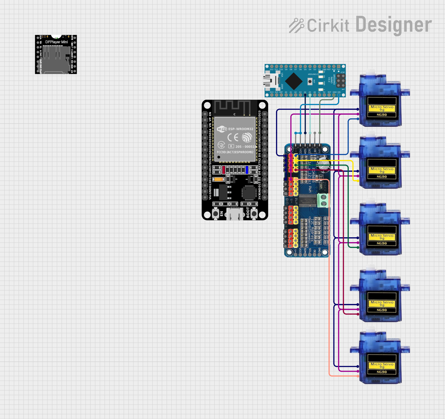
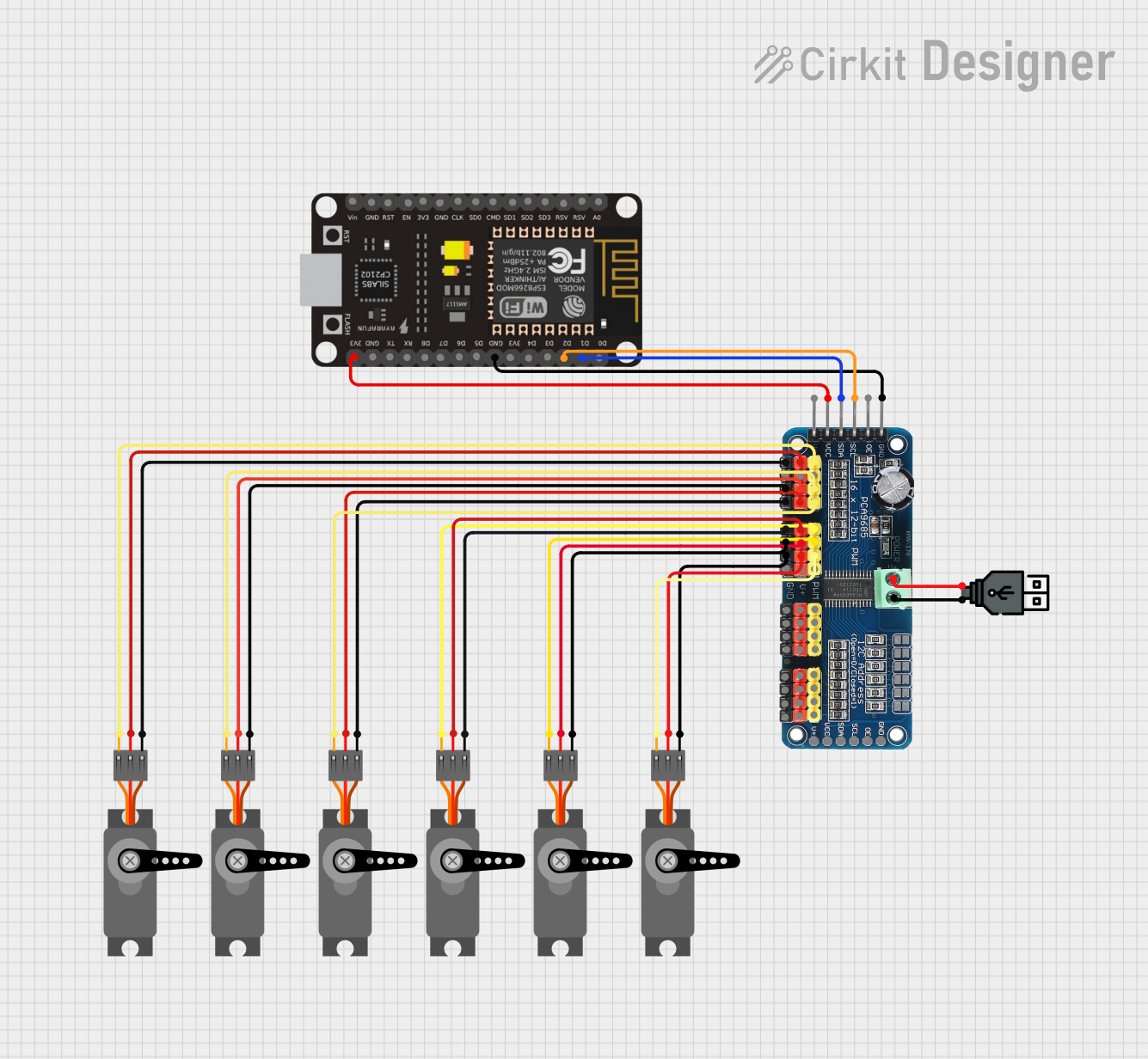
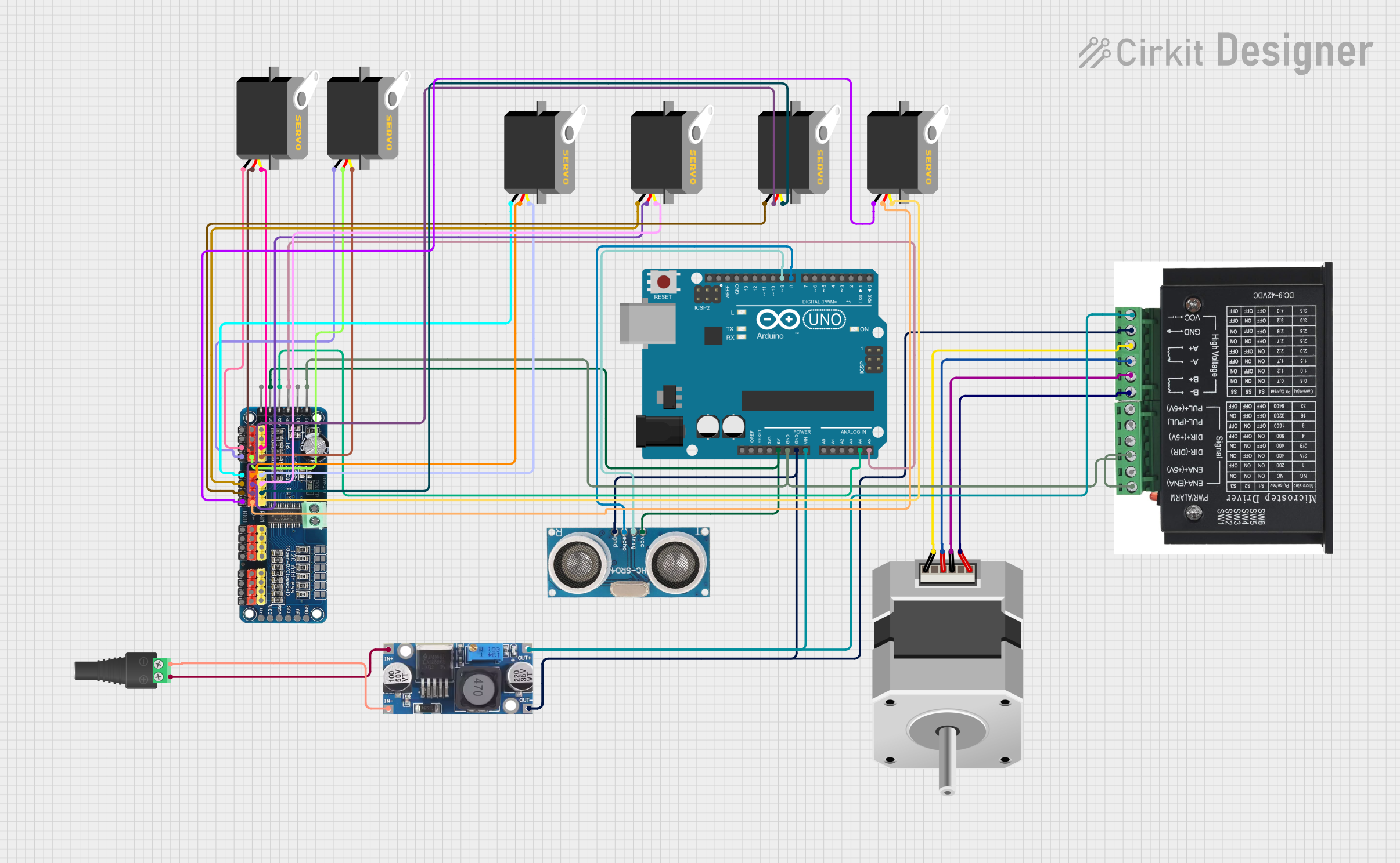
Explore Projects Built with Mini Maestro 12-Channel USB Servo Controller
Common Applications and Use Cases
- Robotics: Controlling robotic arms, legs, or grippers.
- Animatronics: Creating lifelike movements in animatronic figures.
- Automation: Managing servo-driven mechanisms in industrial or DIY projects.
- Prototyping: Testing and developing servo-based systems.
- RC Systems: Enhancing control in remote-controlled vehicles or aircraft.
Technical Specifications
The following table outlines the key technical details of the Mini Maestro 12-Channel USB Servo Controller:
| Specification | Details |
|---|---|
| Manufacturer | Pololu |
| Number of Servo Channels | 12 |
| Input Voltage Range | 5–16 V |
| Logic Voltage | 5 V |
| Communication Interfaces | USB, TTL serial, hobby RC |
| Servo Pulse Range | 64–3280 µs (configurable) |
| Current Consumption | 40 mA (typical, without servos connected) |
| Dimensions | 1.20" × 2.10" × 0.125" (30 mm × 53 mm × 3 mm) |
| Weight | 5.5 g (without header pins) |
| Operating Temperature | -20°C to 70°C |
Pin Configuration and Descriptions
The Mini Maestro 12-Channel USB Servo Controller has a straightforward pin layout. Below is a table describing the key pins:
| Pin Name | Description |
|---|---|
| VIN | Power input for the servos (5–16 V). |
| GND | Ground connection. |
| SERVO 0–11 | Servo signal output pins (12 total). |
| TX | TTL serial transmit pin for communication. |
| RX | TTL serial receive pin for communication. |
| RC IN | Input for hobby RC signals. |
| USB | USB interface for configuration and control. |
| RESET | Resets the controller. |
Usage Instructions
How to Use the Mini Maestro in a Circuit
- Power the Controller: Connect a power source (5–16 V) to the VIN and GND pins. Ensure the power supply can handle the current requirements of all connected servos.
- Connect Servos: Attach the servo signal wires to the SERVO 0–11 pins. Connect the servo power and ground wires to the appropriate power source.
- Connect to a Computer: Use a USB cable to connect the Mini Maestro to your computer for configuration and control.
- Install Software: Download and install the Pololu Maestro Control Center software from the Pololu website. This software allows you to configure servo settings, write scripts, and test servo movements.
- Configure Settings: Use the software to set servo parameters such as position limits, speed, and acceleration.
- Control the Servos: You can control the servos via USB, TTL serial commands, or RC signals, depending on your application.
Important Considerations and Best Practices
- Power Supply: Ensure your power supply can provide sufficient current for all connected servos. A separate power supply for the servos is recommended for high-current applications.
- Signal Interference: Keep servo wires as short as possible to minimize signal interference.
- Heat Management: Avoid overloading the controller or servos, as excessive current can cause overheating.
- Firmware Updates: Check for firmware updates on the Pololu website to ensure optimal performance and compatibility.
Example: Controlling Servos with Arduino UNO
The Mini Maestro can be controlled via TTL serial communication with an Arduino UNO. Below is an example code snippet:
#include <SoftwareSerial.h>

// Define RX and TX pins for communication with the Mini Maestro
SoftwareSerial maestroSerial(10, 11); // RX = pin 10, TX = pin 11

void setup() {
  maestroSerial.begin(9600); // Set baud rate to 9600
}

void setServoTarget(uint8_t channel, uint16_t target) {
  // Sends a command to set the target position of a servo
  // Channel: Servo channel (0–11)
  // Target: Position in quarter-microseconds (e.g., 6000 = 1500 µs)
  maestroSerial.write(0x84);          // Command byte: Set Target
  maestroSerial.write(channel);      // Servo channel
  maestroSerial.write(target & 0x7F); // Lower 7 bits of target
  maestroSerial.write(target >> 7 & 0x7F); // Upper 7 bits of target
}

void loop() {
  setServoTarget(0, 6000); // Move servo on channel 0 to 1500 µs position
  delay(1000);             // Wait 1 second
  setServoTarget(0, 7000); // Move servo on channel 0 to 1750 µs position
  delay(1000);             // Wait 1 second
}
Notes:
- Ensure the Mini Maestro is configured to accept serial commands.
- Adjust the
channelandtargetvalues as needed for your application.
Troubleshooting and FAQs
Common Issues and Solutions
Servos Not Moving:
- Verify that the power supply is connected and providing sufficient voltage/current.
- Check that the servo signal wires are connected to the correct pins.
- Ensure the servo parameters (e.g., position limits) are correctly configured in the software.
USB Connection Not Recognized:
- Confirm that the USB cable is functional and properly connected.
- Install the required drivers from the Pololu website.
- Try a different USB port or computer.
Erratic Servo Movements:
- Check for loose or damaged connections.
- Ensure the power supply is stable and not overloaded.
- Reduce the length of servo wires to minimize interference.
Controller Overheating:
- Avoid exceeding the current limits of the controller.
- Use a heat sink or fan if necessary.
FAQs
Q: Can I control the Mini Maestro without a computer?
A: Yes, the Mini Maestro can operate independently using its internal scripting capabilities or by receiving commands via TTL serial or RC signals.
Q: What is the maximum number of servos I can control?
A: The Mini Maestro 12-Channel model can control up to 12 servos. For more channels, consider other models in the Maestro series.
Q: Can I use the Mini Maestro with 3.3 V logic devices?
A: The Mini Maestro uses 5 V logic. You may need a level shifter to interface with 3.3 V devices.
Q: Is the Mini Maestro compatible with Linux or macOS?
A: Yes, the Pololu Maestro Control Center software is available for Windows, Linux, and macOS.
By following this documentation, you can effectively utilize the Mini Maestro 12-Channel USB Servo Controller for your projects.