Cirkit Designer
Your all-in-one circuit design IDE
Home /
Component Documentation
How to Use 12V Geared Motor: Examples, Pinouts, and Specs
Introduction
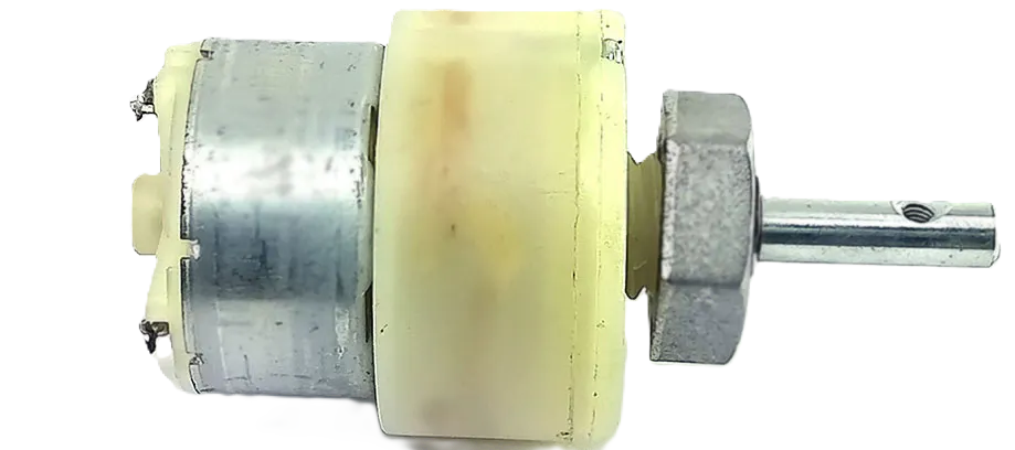
A 12V geared motor is an electromechanical device that combines a 12-volt DC motor with a gearbox. The gearbox is designed to reduce the high-speed rotation of the motor to a slower speed while increasing torque. This type of motor is widely used in applications where precise speed control and higher torque are necessary, such as in robotics, automatic doors, and hobbyist projects.
Explore Projects Built with 12V Geared Motor
Battery-Powered Directional Control for 12V Geared Motors
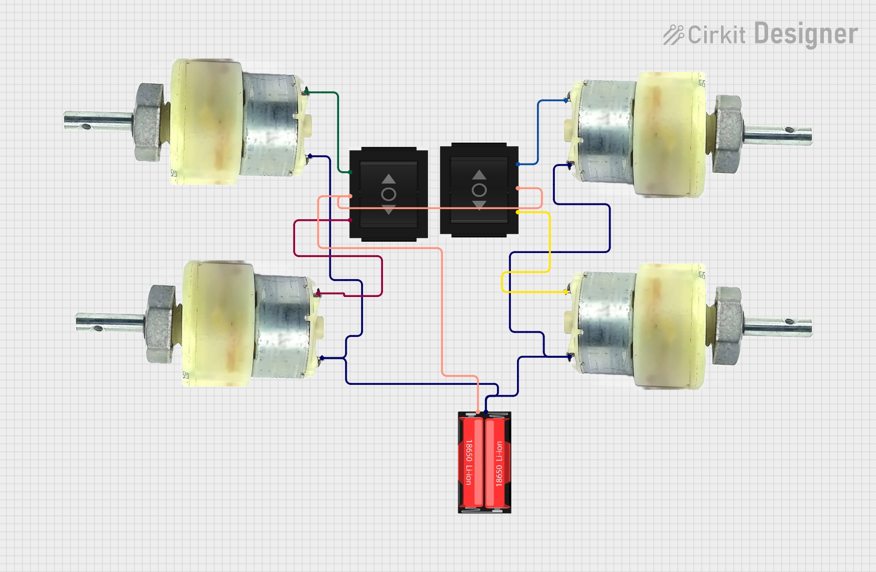
This circuit consists of four 12V geared motors and two directional switches, all powered by a single 18650 Li-Ion battery. The directional switches are used to control the polarity of the voltage applied to the motors, allowing for the reversal of motor direction. The battery's negative terminal is connected to one terminal of each motor, while its positive terminal is connected to the input of both directional switches, which then selectively power the other terminals of the motors.
12V Geared Motor Control with Diode Protection and LED Indicator
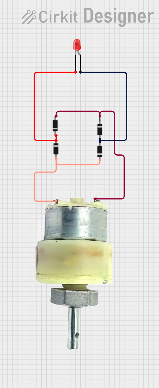
This circuit consists of a 12V geared motor and a red LED, with multiple diodes arranged to provide protection and control the current flow. The diodes are configured to ensure proper operation of the motor and LED, likely providing reverse polarity protection and current regulation.
12V Battery-Powered Motor Control with Voltage Regulation and Charge Management
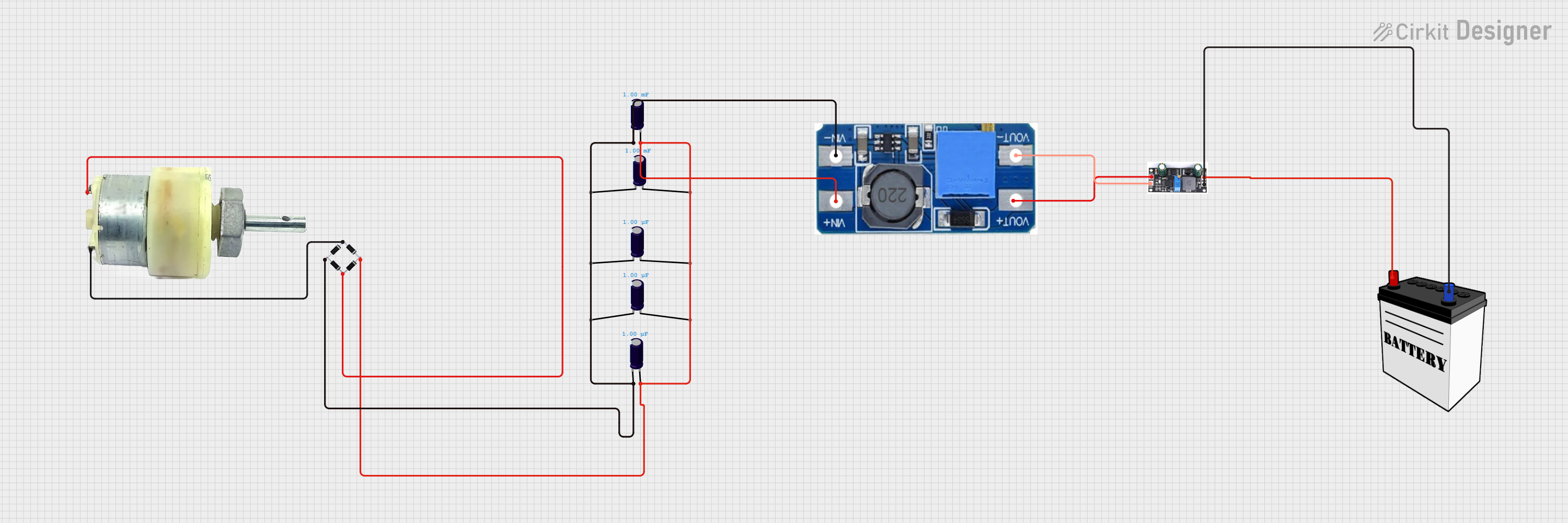
This circuit features a 12V geared motor powered through a bridge rectifier, which suggests that the motor can be driven by an AC or pulsating DC source. The bridge rectifier's output is smoothed by electrolytic capacitors and then fed into a step-up boost power converter, indicating that the circuit is designed to increase the voltage to a higher level. Finally, the output of the boost converter is connected to a charge controller, which is also connected to a 12V battery, suggesting that the circuit is intended to charge the battery while powering the motor.
12V Battery-Powered Motor Control Circuit
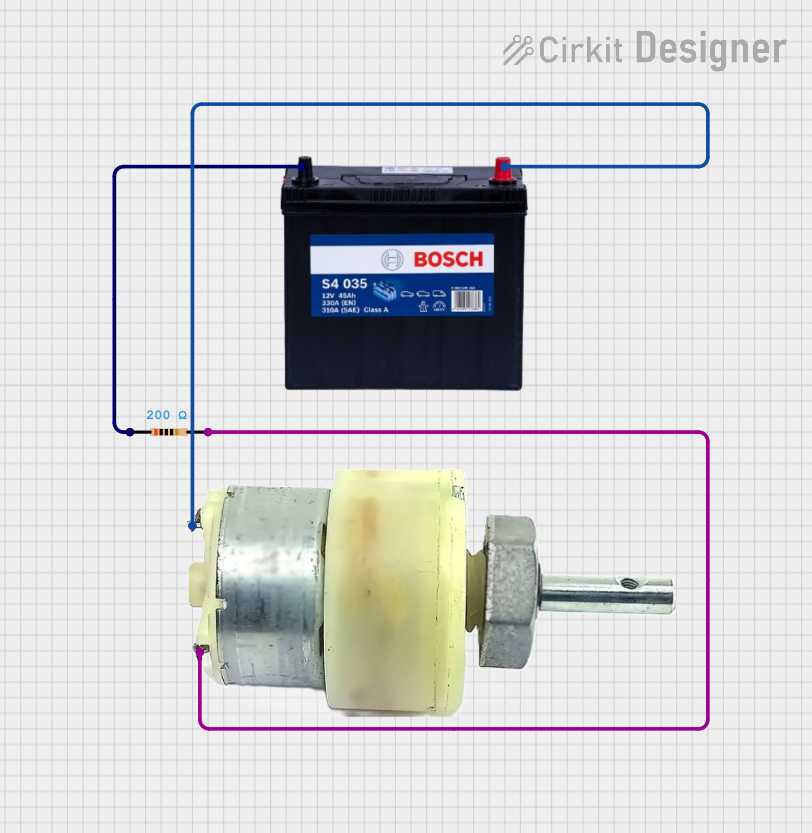
This circuit consists of a 12V 200Ah battery connected to a 12V geared motor, with a 200 Ohm resistor in series with one of the motor's terminals. The battery provides power to the motor, and the resistor limits the current flowing into the motor, potentially to control speed or to protect the motor from excessive current.
Explore Projects Built with 12V Geared Motor
Battery-Powered Directional Control for 12V Geared Motors
This circuit consists of four 12V geared motors and two directional switches, all powered by a single 18650 Li-Ion battery. The directional switches are used to control the polarity of the voltage applied to the motors, allowing for the reversal of motor direction. The battery's negative terminal is connected to one terminal of each motor, while its positive terminal is connected to the input of both directional switches, which then selectively power the other terminals of the motors.
12V Geared Motor Control with Diode Protection and LED Indicator
This circuit consists of a 12V geared motor and a red LED, with multiple diodes arranged to provide protection and control the current flow. The diodes are configured to ensure proper operation of the motor and LED, likely providing reverse polarity protection and current regulation.
12V Battery-Powered Motor Control with Voltage Regulation and Charge Management
This circuit features a 12V geared motor powered through a bridge rectifier, which suggests that the motor can be driven by an AC or pulsating DC source. The bridge rectifier's output is smoothed by electrolytic capacitors and then fed into a step-up boost power converter, indicating that the circuit is designed to increase the voltage to a higher level. Finally, the output of the boost converter is connected to a charge controller, which is also connected to a 12V battery, suggesting that the circuit is intended to charge the battery while powering the motor.
12V Battery-Powered Motor Control Circuit
This circuit consists of a 12V 200Ah battery connected to a 12V geared motor, with a 200 Ohm resistor in series with one of the motor's terminals. The battery provides power to the motor, and the resistor limits the current flowing into the motor, potentially to control speed or to protect the motor from excessive current.
Common Applications and Use Cases
- Robotics and automation systems
- Hobbyist projects (e.g., RC cars, model trains)
- Actuators for mechanical systems
- Automatic door openers
- Small electric vehicles
Technical Specifications
Key Technical Details
- Rated Voltage: 12V DC
- No-load Speed: Typically 10 to 1000 RPM (varies by gearbox ratio)
- Rated Torque: Varies with gearbox ratio and motor power
- Operating Temperature Range: -10°C to +60°C
Pin Configuration and Descriptions
| Pin Number | Description | Notes |
|---|---|---|
| 1 | Motor Positive (M+) | Connect to 12V power supply |
| 2 | Motor Negative (M-) | Connect to ground |
Usage Instructions
How to Use the Component in a Circuit
- Power Supply: Ensure that the power supply is capable of delivering 12V and sufficient current for the motor's operation.
- Motor Driver: Use a motor driver or an H-bridge circuit to control the direction and speed of the motor.
- PWM Control: For speed control, use Pulse Width Modulation (PWM) through a microcontroller like an Arduino UNO.
- Mounting: Secure the motor firmly to prevent movement that could lead to mechanical wear or electrical issues.
Important Considerations and Best Practices
- Current Draw: Be aware of the motor's current draw, especially at startup, to prevent damage to power supplies or control electronics.
- Heat Dissipation: Ensure adequate ventilation around the motor to prevent overheating.
- Gearbox Load: Do not exceed the rated torque of the gearbox to avoid damage.
- Electrical Noise: Use appropriate filtering or shielding to minimize electrical noise that can interfere with other electronics.
Example Arduino UNO Code
// Example code to control a 12V geared motor with an Arduino UNO
#include <Arduino.h>

const int motorPin = 3; // Connect to the PWM-capable pin on the motor driver

void setup() {
  pinMode(motorPin, OUTPUT);
}

void loop() {
  // Set motor speed (0-255)
  analogWrite(motorPin, 127); // Set to approximately 50% speed
  delay(2000); // Run the motor for 2 seconds

  // Stop the motor
  analogWrite(motorPin, 0);
  delay(1000); // Stop the motor for 1 second

  // Change direction or speed as needed
  // ...
}
Troubleshooting and FAQs
Common Issues Users Might Face
- Motor does not turn: Check power supply and connections.
- Insufficient torque: Verify that the gearbox ratio is suitable for the application.
- Overheating: Ensure the motor is not stalled or overloaded.
Solutions and Tips for Troubleshooting
- Power Supply Issues: Use a multimeter to verify that the power supply is delivering 12V.
- Connection Problems: Check all connections for proper soldering and secure fit.
- Motor Driver: Ensure that the motor driver is functioning correctly and is appropriate for the motor's current requirements.
FAQs
- Q: Can I run the motor at a voltage lower than 12V?
- A: Yes, but the speed and torque will be reduced.
- Q: How do I reverse the motor's direction?
- A: Reverse the polarity of the motor's connections, or use an H-bridge circuit to electronically switch the direction.
- Q: What is the maximum load the motor can handle?
- A: This depends on the specific motor and gearbox combination. Refer to the manufacturer's datasheet for the rated torque and do not exceed it.
This documentation provides a basic overview of the 12V geared motor and how to use it in various applications. Always refer to the specific motor's datasheet for detailed information and specifications.