How to Use NPS4069EVB: Examples, Pinouts, and Specs
Introduction
The NPS4069EVB is an evaluation board developed by Nexperia to demonstrate the capabilities of the NPS4069, a high-efficiency, low-power buck converter. This evaluation board is designed to simplify the testing and evaluation of the NPS4069 in various applications, such as power management systems, battery-powered devices, and industrial electronics. It features adjustable output voltage and current capabilities, making it a versatile tool for engineers and designers.
Explore Projects Built with NPS4069EVB


Explore Projects Built with NPS4069EVB
Common Applications and Use Cases
- Power supply for microcontrollers and low-power devices
- Battery-powered systems
- Industrial control systems
- Consumer electronics
- Prototyping and testing of DC-DC conversion circuits
Technical Specifications
Key Technical Details
- Input Voltage Range: 4.5 V to 40 V
- Output Voltage Range: Adjustable from 0.8 V to 15 V
- Output Current: Up to 2 A
- Switching Frequency: 500 kHz (typical)
- Efficiency: Up to 90% (depending on load and input/output conditions)
- Operating Temperature Range: -40°C to +125°C
- Dimensions: Compact PCB layout for easy integration
Pin Configuration and Descriptions
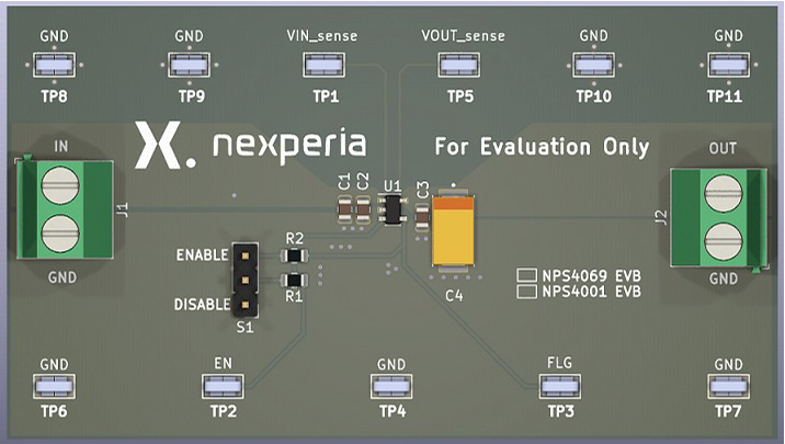
The NPS4069EVB features several key pins and connectors for input, output, and control. The table below provides a detailed description of each pin:
| Pin/Connector | Label | Description |
|---|---|---|
| J1 | VIN | Input voltage terminal (4.5 V to 40 V). Connect the power source here. |
| J2 | GND | Ground terminal. Connect to the ground of the power source. |
| J3 | VOUT | Output voltage terminal. Connect the load here. |
| J4 | EN | Enable pin. Apply a logic HIGH to enable the converter, or LOW to disable it. |
| JP1 | VOUT Adjust | Jumper to adjust the output voltage. Use external resistors for fine-tuning. |
| TP1 | Test Point | Test point for monitoring the output voltage. |
| TP2 | Test Point | Test point for monitoring the input voltage. |
Usage Instructions
How to Use the NPS4069EVB in a Circuit
Power Supply Connection:
- Connect the input voltage (4.5 V to 40 V) to the
VINterminal (J1). - Connect the ground of the power source to the
GNDterminal (J2).
- Connect the input voltage (4.5 V to 40 V) to the
Load Connection:
- Connect the load to the
VOUTterminal (J3). - Ensure the load does not exceed the maximum output current of 2 A.
- Connect the load to the
Enable the Converter:
- Use the
ENpin (J4) to enable or disable the converter. Apply a logic HIGH (e.g., 3.3 V or 5 V) to enable the device.
- Use the
Adjust Output Voltage:
- Use the
VOUT Adjustjumper (JP1) to set the desired output voltage. - For fine-tuning, connect external resistors to the appropriate test points.
- Use the
Monitor Performance:
- Use the test points (TP1 and TP2) to monitor the input and output voltages with a multimeter or oscilloscope.
Important Considerations and Best Practices
- Ensure the input voltage is within the specified range (4.5 V to 40 V) to avoid damaging the board.
- Do not exceed the maximum output current of 2 A to prevent overheating or failure.
- Use proper heat dissipation techniques if operating at high loads for extended periods.
- When adjusting the output voltage, verify the settings with a multimeter before connecting sensitive loads.
- Always follow proper ESD precautions when handling the evaluation board.
Example: Connecting to an Arduino UNO
The NPS4069EVB can be used to power an Arduino UNO by providing a stable 5 V output. Below is an example of how to configure the board:
- Set the output voltage to 5 V using the
VOUT Adjustjumper. - Connect the
VOUTterminal (J3) to the Arduino's 5 V pin. - Connect the
GNDterminal (J2) to the Arduino's GND pin.
Here is a simple Arduino sketch to blink an LED while powered by the NPS4069EVB:
// Simple LED Blink Example
// This sketch blinks an LED connected to pin 13 of the Arduino UNO.
// Ensure the NPS4069EVB is providing a stable 5 V to the Arduino.

void setup() {
  pinMode(13, OUTPUT); // Set pin 13 as an output
}

void loop() {
  digitalWrite(13, HIGH); // Turn the LED on
  delay(1000);            // Wait for 1 second
  digitalWrite(13, LOW);  // Turn the LED off
  delay(1000);            // Wait for 1 second
}
Troubleshooting and FAQs
Common Issues and Solutions
No Output Voltage:
- Verify that the input voltage is within the specified range (4.5 V to 40 V).
- Check if the
ENpin is set to logic HIGH to enable the converter. - Ensure the load is properly connected to the
VOUTterminal.
Overheating:
- Ensure the load does not exceed the maximum output current of 2 A.
- Check for proper ventilation and consider adding a heatsink if necessary.
Output Voltage is Incorrect:
- Verify the
VOUT Adjustjumper settings and external resistor values. - Use a multimeter to measure the output voltage and adjust as needed.
- Verify the
Board is Not Powering the Load:
- Check all connections to ensure they are secure.
- Verify that the load is within the board's power capabilities.
FAQs
Q1: Can the NPS4069EVB be used with a battery as the input source?
A1: Yes, the board can be powered by a battery as long as the input voltage is within the range of 4.5 V to 40 V.
Q2: How do I adjust the output voltage precisely?
A2: Use the VOUT Adjust jumper and connect external resistors to fine-tune the output voltage. Refer to the datasheet for resistor value calculations.
Q3: Is the board protected against short circuits?
A3: The NPS4069 includes built-in protection features, but it is recommended to avoid intentional short circuits to prevent damage.
Q4: Can I use the board for currents higher than 2 A?
A4: No, the maximum output current is 2 A. Exceeding this limit may damage the board or reduce its lifespan.