How to Use LM2596 by QQ: Examples, Pinouts, and Specs
Introduction
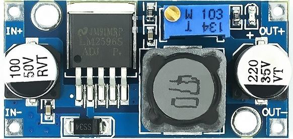
The LM2596 is a step-down (buck) voltage regulator designed to efficiently convert a higher input voltage into a stable, lower output voltage. This component is widely used in power supply applications due to its high efficiency, adjustable output voltage, and built-in thermal protection. It is ideal for powering low-voltage devices from higher-voltage sources, such as batteries or unregulated power supplies.
Explore Projects Built with LM2596 by QQ


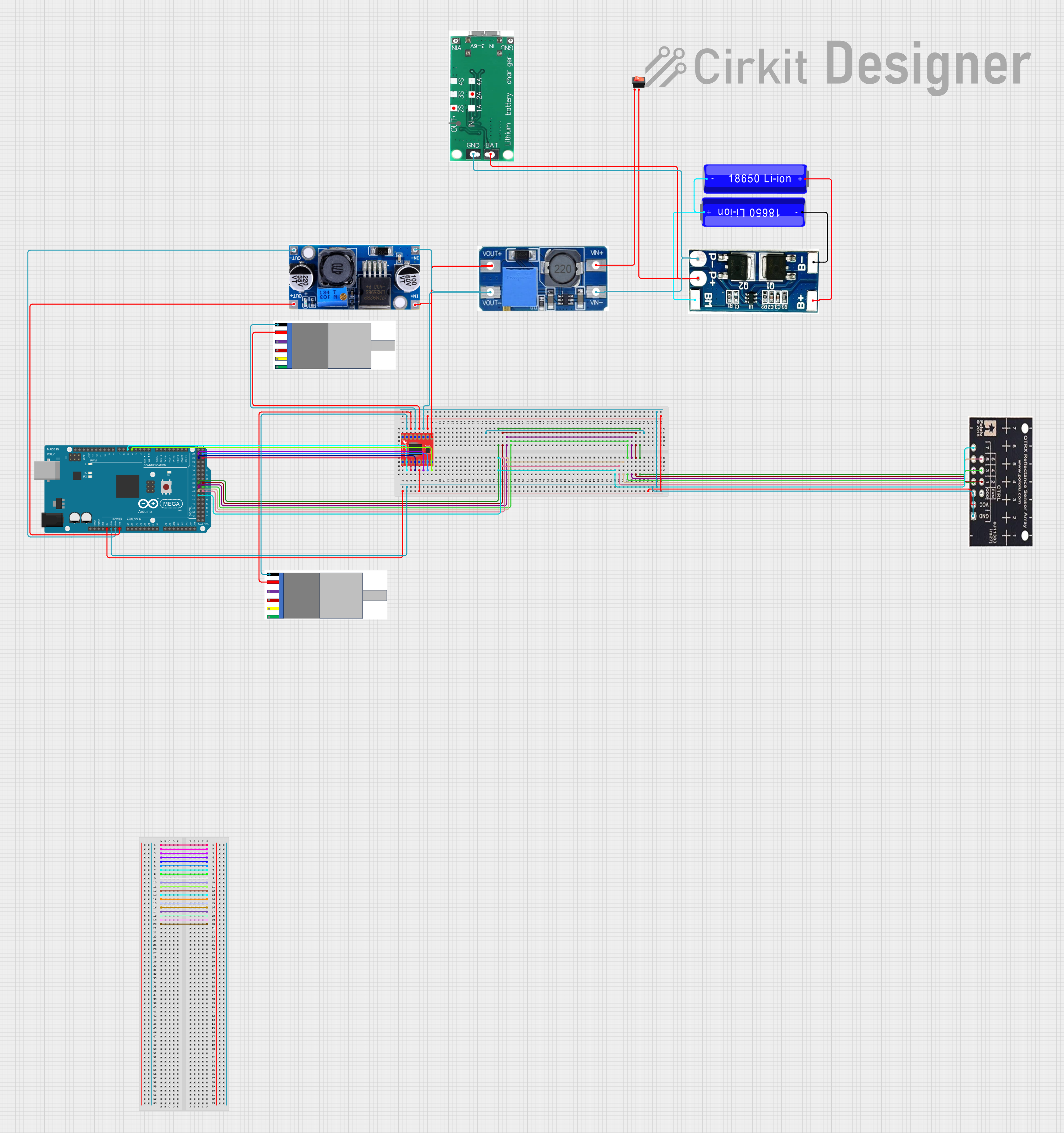
Explore Projects Built with LM2596 by QQ
Common Applications
- DC-DC power supply modules
- Battery-powered devices
- Voltage regulation for microcontrollers and sensors
- LED drivers
- Industrial and automotive electronics
Technical Specifications
The LM2596 is available in various output voltage configurations, including adjustable and fixed options. Below are the key technical details:
General Specifications
| Parameter | Value |
|---|---|
| Input Voltage Range | 4.5V to 40V |
| Output Voltage Range | 1.23V to 37V (adjustable version) |
| Output Current | Up to 3A |
| Efficiency | Up to 90% |
| Switching Frequency | 150 kHz |
| Operating Temperature | -40°C to +125°C |
| Package Type | TO-220, TO-263 (surface-mount) |
Pin Configuration
The LM2596 typically comes in a 5-pin TO-220 or TO-263 package. Below is the pinout description:
| Pin Number | Pin Name | Description |
|---|---|---|
| 1 | VIN | Input voltage (4.5V to 40V) |
| 2 | Output | Regulated output voltage |
| 3 | Ground | Ground connection |
| 4 | Feedback | Feedback pin for adjustable output voltage |
| 5 | ON/OFF | Enable/disable control (optional, not always used) |
Usage Instructions
How to Use the LM2596 in a Circuit
- Input Voltage: Connect the input voltage (VIN) to the LM2596. Ensure the input voltage is within the specified range (4.5V to 40V).
- Output Voltage: For the adjustable version, use a resistor divider network connected to the Feedback pin to set the desired output voltage. For fixed versions, no external resistors are needed.
- Capacitors: Place input and output capacitors close to the regulator to ensure stability and reduce noise. Typical values are:
- Input capacitor: 100 µF electrolytic
- Output capacitor: 220 µF electrolytic
- Inductor: Use an appropriate inductor value (e.g., 33 µH) based on the desired output voltage and current.
- Heat Dissipation: Attach a heatsink if the regulator operates at high currents or in high-temperature environments.
Example Circuit
Below is a basic circuit for the adjustable version of the LM2596:
VIN (4.5V-40V) ----+---- Input (Pin 1)
                   |
                [100 µF]
                   |
                  GND
                   |
                   +---- Output (Pin 2) ----> VOUT (1.23V-37V)
                   |
                [220 µF]
                   |
                  GND
Arduino UNO Example Code
The LM2596 can be used to power an Arduino UNO by stepping down a higher voltage (e.g., 12V) to 5V. Here's an example code snippet to read a sensor powered by the LM2596:
// Example: Reading a sensor powered by LM2596
// Ensure the LM2596 output is set to 5V for the Arduino UNO

const int sensorPin = A0; // Sensor connected to analog pin A0
int sensorValue = 0;      // Variable to store sensor reading

void setup() {
  Serial.begin(9600); // Initialize serial communication
  pinMode(sensorPin, INPUT); // Set sensor pin as input
}

void loop() {
  sensorValue = analogRead(sensorPin); // Read sensor value
  Serial.print("Sensor Value: ");
  Serial.println(sensorValue); // Print sensor value to Serial Monitor
  delay(1000); // Wait 1 second before next reading
}
Important Considerations
- Input Voltage: Ensure the input voltage is at least 3V higher than the desired output voltage for proper regulation.
- Thermal Management: Use a heatsink or ensure adequate ventilation to prevent overheating.
- Load Current: Do not exceed the maximum output current of 3A to avoid damage.
- Feedback Resistors: For adjustable versions, use precision resistors to achieve accurate output voltage.
Troubleshooting and FAQs
Common Issues and Solutions
No Output Voltage
- Check the input voltage; ensure it is within the specified range.
- Verify all connections, especially the ground and feedback pins.
- Inspect the capacitors and inductor for proper values and placement.
Output Voltage is Unstable
- Ensure the input and output capacitors are of the correct value and placed close to the regulator.
- Check for loose connections or poor solder joints.
- Verify the inductor value matches the design requirements.
Regulator Overheating
- Ensure the load current does not exceed 3A.
- Attach a heatsink to the LM2596 or improve ventilation.
- Check for short circuits or excessive input voltage.
Incorrect Output Voltage
- For adjustable versions, verify the resistor divider network values.
- Ensure the Feedback pin is properly connected.
FAQs
Q: Can the LM2596 be used with a battery?
A: Yes, the LM2596 is suitable for battery-powered applications. Ensure the input voltage is within the specified range.
Q: What is the efficiency of the LM2596?
A: The LM2596 can achieve up to 90% efficiency, depending on the input/output voltage and load conditions.
Q: Can I use the LM2596 to power a Raspberry Pi?
A: Yes, the LM2596 can step down a higher voltage (e.g., 12V) to 5V to power a Raspberry Pi. Ensure the output current is sufficient for the Pi and connected peripherals.
Q: Is the LM2596 suitable for audio applications?
A: The LM2596 may introduce switching noise, which can affect audio circuits. Use additional filtering if noise is a concern.
By following this documentation, you can effectively integrate the LM2596 into your projects and troubleshoot common issues.