
How to Use 20 Pin Board: Examples, Pinouts, and Specs
 Design with 20 Pin Board in Cirkit Designer
Introduction
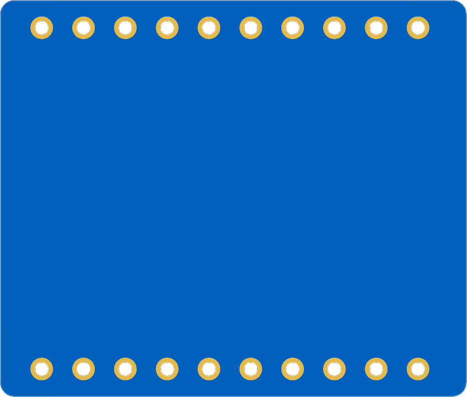
The 20 Pin Board is a versatile prototyping board designed for assembling and testing electronic circuits. It features 20 pins that allow users to connect various electronic components, making it ideal for rapid prototyping and experimentation. This board is commonly used in educational projects, hobbyist applications, and professional circuit development.
Explore Projects Built with 20 Pin Board
 Open Project in Cirkit Designer
 Open Project in Cirkit Designer
 Open Project in Cirkit Designer
 Open Project in Cirkit Designer
Explore Projects Built with 20 Pin Board
Open Project in Cirkit DesignerOpen Project in Cirkit DesignerOpen Project in Cirkit DesignerOpen Project in Cirkit DesignerCommon Applications and Use Cases
- Rapid prototyping of electronic circuits
- Educational projects for learning circuit design
- Testing and debugging of small-scale circuits
- Temporary assembly of components for experimentation
- Integration with microcontrollers like Arduino or Raspberry Pi
Technical Specifications
The 20 Pin Board is a general-purpose prototyping board with the following specifications:
Key Technical Details
| Parameter | Specification |
|---|---|
| Number of Pins | 20 |
| Pin Type | Male or female headers (varies) |
| Board Material | FR4 (fiberglass) or similar |
| Dimensions | Varies (e.g., 50mm x 20mm) |
| Operating Temperature | -40°C to +85°C |
| Compatibility | Breadboards, microcontrollers |
Pin Configuration and Descriptions
The 20 Pin Board typically features a simple pin layout. Below is an example of a standard configuration:
| Pin Number | Description |
|---|---|
| 1-10 | General-purpose I/O (GPIO) pins |
| 11-20 | General-purpose I/O (GPIO) pins |
Note: The exact pin configuration may vary depending on the specific board design. Always refer to the physical layout of your board.
Usage Instructions
How to Use the 20 Pin Board in a Circuit
Prepare the Board:
- Ensure the board is clean and free of debris.
- Identify the pin numbers and their corresponding functions.
Connect Components:
- Use jumper wires or solder components directly to the pins.
- Ensure proper alignment of components to avoid short circuits.
Integrate with Other Devices:
- Connect the board to a breadboard or microcontroller for testing.
- Use male-to-female or male-to-male jumper wires as needed.
Power the Circuit:
- Provide power to the circuit through an external power supply or microcontroller.
- Verify voltage and current requirements of connected components.
Important Considerations and Best Practices
- Avoid Overloading Pins: Ensure the current and voltage ratings of the pins are not exceeded.
- Secure Connections: Use soldering or tight jumper wire connections to prevent loose contacts.
- Label Pins: If the board does not have labeled pins, consider marking them for easier identification.
- Test Continuity: Use a multimeter to check for proper connections before powering the circuit.
Example: Connecting to an Arduino UNO
The 20 Pin Board can be used to expand the I/O capabilities of an Arduino UNO. Below is an example of how to connect and use it:
Circuit Setup
- Connect the 20 Pin Board to the Arduino UNO using jumper wires.
- Assign specific pins on the board to Arduino digital or analog pins.
Sample Code
// Example code for using a 20 Pin Board with Arduino UNO
// This code toggles an LED connected to pin 2 of the 20 Pin Board

const int ledPin = 2; // Pin 2 on the 20 Pin Board connected to an LED

void setup() {
  pinMode(ledPin, OUTPUT); // Set pin 2 as an output
}

void loop() {
  digitalWrite(ledPin, HIGH); // Turn the LED on
  delay(1000);               // Wait for 1 second
  digitalWrite(ledPin, LOW);  // Turn the LED off
  delay(1000);               // Wait for 1 second
}
Note: Ensure the LED is connected with a current-limiting resistor (e.g., 220Ω) to prevent damage.
Troubleshooting and FAQs
Common Issues Users Might Face
Loose Connections:
- Problem: Components or wires are not securely connected to the pins.
- Solution: Check all connections and ensure they are tight. Use soldering if necessary.
Short Circuits:
- Problem: Adjacent pins are accidentally connected, causing a short circuit.
- Solution: Inspect the board for unintended connections and correct them.
Incorrect Pin Mapping:
- Problem: Pins are not correctly identified or connected.
- Solution: Double-check the pin layout and ensure proper mapping to your circuit.
Overloaded Pins:
- Problem: Excessive current or voltage damages the pins.
- Solution: Verify the ratings of the board and connected components before powering the circuit.
FAQs
Q: Can I use the 20 Pin Board with a breadboard?
A: Yes, the 20 Pin Board is compatible with standard breadboards. You can use jumper wires to connect the pins to the breadboard.
Q: Is the board suitable for high-power applications?
A: No, the 20 Pin Board is designed for low-power prototyping. Avoid using it for high-current or high-voltage circuits.
Q: How do I clean the board after soldering?
A: Use isopropyl alcohol and a soft brush to remove flux residue and ensure clean connections.
Q: Can I reuse the board after soldering components?
A: Yes, but desoldering components may damage the board or pins. Use caution when reusing.
By following this documentation, users can effectively utilize the 20 Pin Board for their prototyping and circuit development needs.