Cirkit Designer Logo
Cirkit Designer
Your all-in-one circuit design IDE
Home / 
Component Documentation

How to Use s: Examples, Pinouts, and Specs

Image of s
Cirkit Designer LogoDesign with s in Cirkit Designer

Introduction

The "S" component, manufactured by S, is a versatile electronic element commonly used in circuit design. It often represents a switch or a signal in various applications. This component is integral in controlling the flow of current or transmitting signals in both analog and digital circuits. Its simplicity and adaptability make it a fundamental building block in electronics.

Explore Projects Built with s

Use Cirkit Designer to design, explore, and prototype these projects online. Some projects support real-time simulation. Click "Open Project" to start designing instantly!
NFC-Enabled Access Control System with Real-Time Clock and OLED Display
Image of doorlock: A project utilizing s in a practical application
This circuit is designed as an access control system with time-tracking capabilities. It uses an NFC/RFID reader for authentication, a real-time clock for time-stamping events, and an OLED display for user interface, all controlled by a T8_S3 microcontroller. A relay module actuates a magnetic lock, and a button switch provides additional user input, with a switching power supply delivering the necessary voltages.
Cirkit Designer LogoOpen Project in Cirkit Designer
NFC-Enabled Access Control System with Time Logging
Image of doorlock: A project utilizing s in a practical application
This circuit is designed for access control with time tracking capabilities. It features an NFC/RFID reader for authentication, an RTC module (DS3231) for real-time clock functionality, and an OLED display for user interaction. A 12V relay controls a magnetic lock, which is activated upon successful NFC/RFID authentication, and a button switch is likely used for manual operation or input. The T8_S3 microcontroller serves as the central processing unit, interfacing with the NFC/RFID reader, RTC, OLED, and relay to manage the access control logic.
Cirkit Designer LogoOpen Project in Cirkit Designer
Beelink Mini S12 N95 and Arduino UNO Based Fingerprint Authentication System with ESP32 CAM
Image of design 3: A project utilizing s in a practical application
This circuit features a Beelink MINI S12 N95 computer connected to a 7-inch display via HDMI for video output and two USB connections for power and touch screen functionality. An Arduino UNO is interfaced with a fingerprint scanner for biometric input. The Beelink MINI S12 N95 is powered by a PC power supply, which in turn is connected to a 240V power source. Additionally, an ESP32 CAM module is powered and programmed via a USB plug and an FTDI programmer, respectively, for wireless camera capabilities.
Cirkit Designer LogoOpen Project in Cirkit Designer
ESP32-S3 Based Vibration Detection System with TFT Display and Power Backup
Image of IOT Thesis: A project utilizing s in a practical application
This circuit features an ESP32-S3 microcontroller connected to various peripherals including an ADXL355 accelerometer, an SW-420 vibration sensor, a buzzer module, and an ILI9341 TFT display. The ESP32-S3 manages sensor inputs and provides output to the display and buzzer. Power management is handled by a 12V to 5V step-down converter, and a UPS ensures uninterrupted power supply, with a rocker switch to control the power flow.
Cirkit Designer LogoOpen Project in Cirkit Designer

Explore Projects Built with s

Use Cirkit Designer to design, explore, and prototype these projects online. Some projects support real-time simulation. Click "Open Project" to start designing instantly!
Image of doorlock: A project utilizing s in a practical application
NFC-Enabled Access Control System with Real-Time Clock and OLED Display
This circuit is designed as an access control system with time-tracking capabilities. It uses an NFC/RFID reader for authentication, a real-time clock for time-stamping events, and an OLED display for user interface, all controlled by a T8_S3 microcontroller. A relay module actuates a magnetic lock, and a button switch provides additional user input, with a switching power supply delivering the necessary voltages.
Cirkit Designer LogoOpen Project in Cirkit Designer
Image of doorlock: A project utilizing s in a practical application
NFC-Enabled Access Control System with Time Logging
This circuit is designed for access control with time tracking capabilities. It features an NFC/RFID reader for authentication, an RTC module (DS3231) for real-time clock functionality, and an OLED display for user interaction. A 12V relay controls a magnetic lock, which is activated upon successful NFC/RFID authentication, and a button switch is likely used for manual operation or input. The T8_S3 microcontroller serves as the central processing unit, interfacing with the NFC/RFID reader, RTC, OLED, and relay to manage the access control logic.
Cirkit Designer LogoOpen Project in Cirkit Designer
Image of design 3: A project utilizing s in a practical application
Beelink Mini S12 N95 and Arduino UNO Based Fingerprint Authentication System with ESP32 CAM
This circuit features a Beelink MINI S12 N95 computer connected to a 7-inch display via HDMI for video output and two USB connections for power and touch screen functionality. An Arduino UNO is interfaced with a fingerprint scanner for biometric input. The Beelink MINI S12 N95 is powered by a PC power supply, which in turn is connected to a 240V power source. Additionally, an ESP32 CAM module is powered and programmed via a USB plug and an FTDI programmer, respectively, for wireless camera capabilities.
Cirkit Designer LogoOpen Project in Cirkit Designer
Image of IOT Thesis: A project utilizing s in a practical application
ESP32-S3 Based Vibration Detection System with TFT Display and Power Backup
This circuit features an ESP32-S3 microcontroller connected to various peripherals including an ADXL355 accelerometer, an SW-420 vibration sensor, a buzzer module, and an ILI9341 TFT display. The ESP32-S3 manages sensor inputs and provides output to the display and buzzer. Power management is handled by a 12V to 5V step-down converter, and a UPS ensures uninterrupted power supply, with a rocker switch to control the power flow.
Cirkit Designer LogoOpen Project in Cirkit Designer

Common Applications and Use Cases

  • Switching Circuits: Used to control the on/off state of a circuit.
  • Signal Transmission: Acts as a placeholder or representation for signals in circuit diagrams.
  • Logic Circuits: Employed in digital systems to represent binary states (high/low).
  • Prototyping and Testing: Frequently used in breadboard setups for quick circuit design.

Technical Specifications

The "S" component is abstract in nature and does not have fixed electrical characteristics. However, when implemented as a physical switch or signal, the following specifications are typically considered:

General Specifications

Parameter Value/Description
Voltage Rating Depends on the circuit design (e.g., 5V, 12V)
Current Rating Varies based on the application (e.g., 10mA to 1A)
Signal Type Analog or Digital
Form Factor Abstract or physical (e.g., toggle switch)

Pin Configuration and Descriptions

If the "S" component is implemented as a physical switch, the pin configuration may resemble the following:

Pin Number Name Description
1 Input Input terminal for the signal or current
2 Output Output terminal for the signal or current

Usage Instructions

The "S" component can be used in a variety of ways depending on its implementation. Below are general guidelines for its usage:

Using "S" as a Switch

  1. Connect the Input and Output: Attach the input terminal to the power source or signal source and the output terminal to the load or next stage in the circuit.
  2. Control the State: Use a mechanical or electronic mechanism to toggle the switch between on (closed) and off (open) states.
  3. Ensure Proper Ratings: Verify that the voltage and current ratings of the switch match the circuit requirements.

Using "S" as a Signal

  1. Define the Signal: In circuit diagrams, use "S" to represent a signal path or a control line.
  2. Label Clearly: Ensure that the signal's purpose is clearly labeled to avoid confusion during implementation.
  3. Connect Appropriately: Route the signal to the intended components, such as microcontrollers, sensors, or actuators.

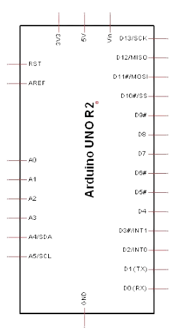
Example: Connecting "S" to an Arduino UNO

If "S" is used as a switch in a digital circuit, it can be connected to an Arduino UNO as follows:

Circuit Setup

  • Connect one terminal of the switch to a digital input pin on the Arduino (e.g., pin 2).
  • Connect the other terminal to ground.
  • Use a pull-up resistor (internal or external) to ensure a stable signal.

Arduino Code

// Define the pin connected to the switch
const int switchPin = 2;

// Variable to store the switch state
int switchState = 0;

void setup() {
  // Set the switch pin as input with an internal pull-up resistor
  pinMode(switchPin, INPUT_PULLUP);

  // Initialize serial communication for debugging
  Serial.begin(9600);
}

void loop() {
  // Read the state of the switch (LOW = pressed, HIGH = not pressed)
  switchState = digitalRead(switchPin);

  // Print the switch state to the Serial Monitor
  if (switchState == LOW) {
    Serial.println("Switch is pressed");
  } else {
    Serial.println("Switch is not pressed");
  }

  // Add a small delay to avoid spamming the Serial Monitor
  delay(200);
}

Important Considerations

  • Debouncing: When using "S" as a physical switch, implement debouncing techniques to avoid false triggering due to mechanical noise.
  • Signal Integrity: Ensure that signal paths are properly shielded and routed to minimize interference.
  • Power Ratings: Always check the voltage and current ratings of the switch or signal path to prevent damage.

Troubleshooting and FAQs

Common Issues

  1. Switch Not Responding

    • Cause: Loose connections or incorrect wiring.
    • Solution: Double-check all connections and ensure proper contact.
  2. Signal Interference

    • Cause: Poor routing or lack of shielding.
    • Solution: Use shielded cables and maintain proper spacing between signal lines.
  3. Arduino Not Detecting Switch State

    • Cause: Missing pull-up resistor or incorrect pin configuration.
    • Solution: Enable the internal pull-up resistor in the Arduino code or add an external resistor.

FAQs

  1. Can "S" be used for both analog and digital signals?

    • Yes, "S" can represent both analog and digital signals depending on the circuit design.
  2. What is the typical lifespan of a physical switch?

    • The lifespan varies by type but is typically rated in thousands to millions of cycles.
  3. How do I debounce a switch in software?

    • Use a delay or a state-change detection algorithm in your code to filter out noise.

By following this documentation, users can effectively integrate the "S" component into their electronic designs, ensuring reliable and efficient operation.