How to Use Adafruit Metro M7 with microSD: Examples, Pinouts, and Specs
Introduction
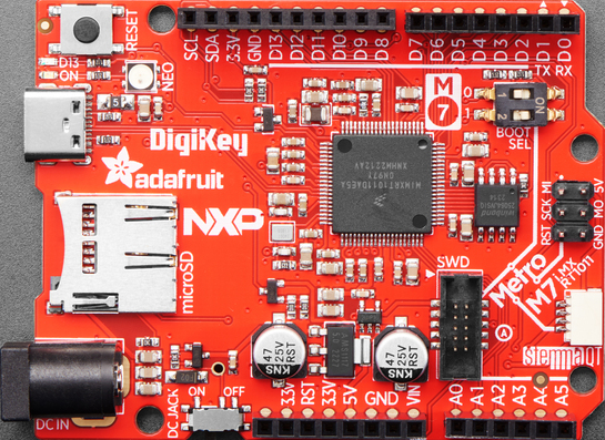
The Adafruit Metro M7 with microSD is a high-performance microcontroller board powered by the NXP iMX RT1011, featuring an ARM Cortex-M7 processor running at 500 MHz. This board is designed for demanding applications that require significant processing power, such as real-time data processing, machine learning, and multimedia projects. It includes a built-in microSD card slot for convenient data storage and is fully compatible with the Arduino IDE, making it accessible to both beginners and advanced users.
Explore Projects Built with Adafruit Metro M7 with microSD

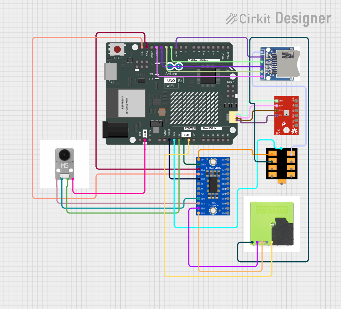
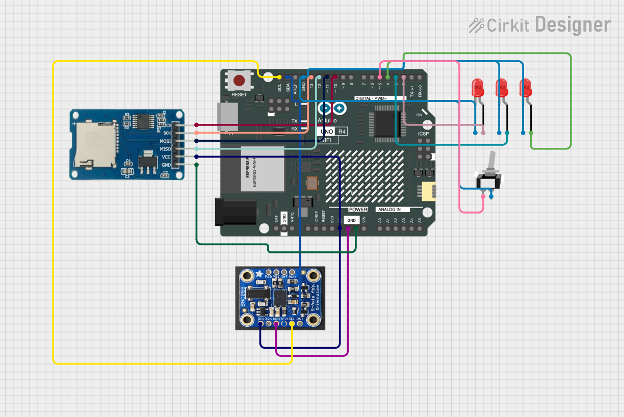
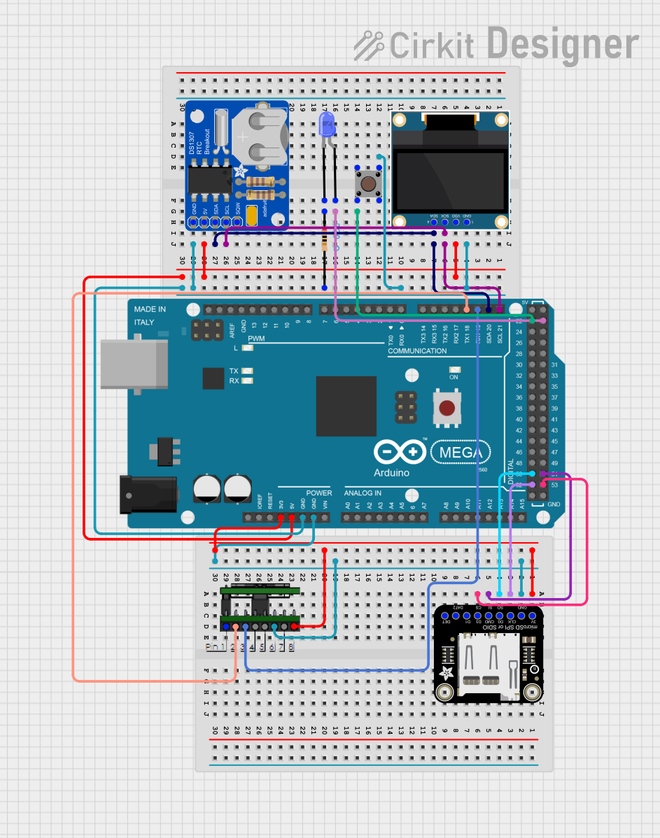
Explore Projects Built with Adafruit Metro M7 with microSD
Common Applications and Use Cases
- Real-time data acquisition and processing
- Machine learning and AI applications
- Robotics and automation systems
- Audio and video processing
- IoT (Internet of Things) devices
- Data logging and storage using the microSD card
Technical Specifications
Below are the key technical details of the Adafruit Metro M7 with microSD:
| Specification | Details |
|---|---|
| Processor | ARM Cortex-M7, NXP iMX RT1011 @ 500 MHz |
| Flash Memory | 512 KB |
| RAM | 128 KB |
| MicroSD Card Slot | Yes |
| Operating Voltage | 3.3V |
| Input Voltage (VIN) | 5V |
| USB Interface | USB Type-C |
| GPIO Pins | 24 |
| Analog Input Pins | 8 |
| PWM Output Pins | 12 |
| Communication Interfaces | UART, I2C, SPI |
| Dimensions | 71.1mm x 53.4mm |
| Weight | 20g |
Pin Configuration and Descriptions
The Adafruit Metro M7 features a standard pinout for easy integration into projects. Below is the pin configuration:
| Pin | Type | Description |
|---|---|---|
| VIN | Power Input | 5V input for powering the board externally. |
| 3.3V | Power Output | 3.3V output for powering external components. |
| GND | Ground | Ground connection. |
| A0-A7 | Analog Input | 8 analog input pins (12-bit resolution). |
| D0-D13 | Digital I/O | 14 digital I/O pins, 12 of which support PWM. |
| SDA | I2C Data | I2C data line. |
| SCL | I2C Clock | I2C clock line. |
| TX | UART TX | UART transmit pin. |
| RX | UART RX | UART receive pin. |
| MOSI | SPI Data Out | SPI Master Out, Slave In. |
| MISO | SPI Data In | SPI Master In, Slave Out. |
| SCK | SPI Clock | SPI clock line. |
| microSD | Storage | microSD card slot for data storage. |
Usage Instructions
How to Use the Component in a Circuit
Powering the Board:
- Connect the board to your computer using a USB Type-C cable for power and programming.
- Alternatively, supply 5V to the VIN pin for external power.
Programming the Board:
- Install the Arduino IDE and add the Adafruit Metro M7 board support package via the Boards Manager.
- Select the correct board and port in the Arduino IDE.
- Write or upload your code to the board.
Using the microSD Card Slot:
- Insert a formatted microSD card into the slot.
- Use the Arduino
SDlibrary to read and write data to the card.
Connecting Peripherals:
- Use the GPIO pins to connect sensors, actuators, or other peripherals.
- Ensure that all connected components operate at 3.3V logic levels to avoid damage.
Important Considerations and Best Practices
- Voltage Levels: The GPIO pins operate at 3.3V. Avoid applying 5V to these pins to prevent damage.
- Power Supply: If using an external power source, ensure it provides a stable 5V to the VIN pin.
- Heat Management: The ARM Cortex-M7 processor is powerful and may generate heat during intensive tasks. Ensure proper ventilation.
- microSD Card Compatibility: Use microSD cards formatted as FAT16 or FAT32 for best compatibility.
Example Code for Arduino IDE
The following example demonstrates how to read and write data to the microSD card:
#include <SD.h>  // Include the SD library
#include <SPI.h> // Include the SPI library

// Define the chip select pin for the microSD card
const int chipSelect = 10;

void setup() {
  // Initialize serial communication for debugging
  Serial.begin(115200);
  while (!Serial) {
    ; // Wait for the serial port to connect
  }

  // Initialize the microSD card
  Serial.print("Initializing microSD card...");
  if (!SD.begin(chipSelect)) {
    Serial.println("Card failed, or not present.");
    return; // Stop if the card is not detected
  }
  Serial.println("Card initialized successfully.");

  // Create and write to a file
  File dataFile = SD.open("example.txt", FILE_WRITE);
  if (dataFile) {
    dataFile.println("Hello, Adafruit Metro M7!");
    dataFile.close(); // Close the file to save changes
    Serial.println("Data written to example.txt.");
  } else {
    Serial.println("Error opening example.txt.");
  }
}

void loop() {
  // Read the file and print its contents
  File dataFile = SD.open("example.txt");
  if (dataFile) {
    Serial.println("Reading from example.txt:");
    while (dataFile.available()) {
      Serial.write(dataFile.read());
    }
    dataFile.close(); // Close the file after reading
  } else {
    Serial.println("Error opening example.txt.");
  }
  delay(5000); // Wait 5 seconds before reading again
}
Troubleshooting and FAQs
Common Issues Users Might Face
Board Not Detected in Arduino IDE:
- Ensure the correct board and port are selected in the Arduino IDE.
- Install the required board support package from the Boards Manager.
microSD Card Not Recognized:
- Verify that the card is properly inserted into the slot.
- Ensure the card is formatted as FAT16 or FAT32.
- Check the chip select pin configuration in your code.
Overheating:
- If the board becomes excessively hot, reduce the processing load or improve ventilation.
GPIO Pin Damage:
- Ensure all connected components operate at 3.3V logic levels. Use level shifters if necessary.
Solutions and Tips for Troubleshooting
- Debugging with Serial Monitor: Use the Serial Monitor in the Arduino IDE to print debug messages and identify issues.
- Testing microSD Card: Test the microSD card on another device to ensure it is functional.
- Resetting the Board: Press the reset button on the board to restart it if it becomes unresponsive.
- Consulting Documentation: Refer to the Adafruit Metro M7 product page and forums for additional support.
By following this documentation, you can effectively utilize the Adafruit Metro M7 with microSD for your high-performance projects.