
How to Use Pushbutton_2P: Examples, Pinouts, and Specs
 Design with Pushbutton_2P in Cirkit Designer
Introduction
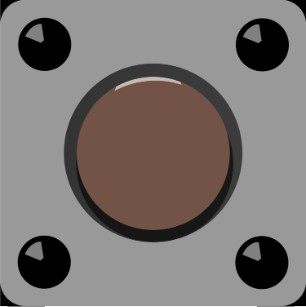
The Pushbutton_2P is a versatile pushbutton switch manufactured by Custom, with the part ID PushButton_2p. This component features two poles, enabling it to control two separate circuits or functions simultaneously with a single press. It is commonly used in applications requiring momentary switching, such as user interfaces, control panels, and prototyping.
Explore Projects Built with Pushbutton_2P
 Open Project in Cirkit Designer
 Open Project in Cirkit Designer
 Open Project in Cirkit Designer
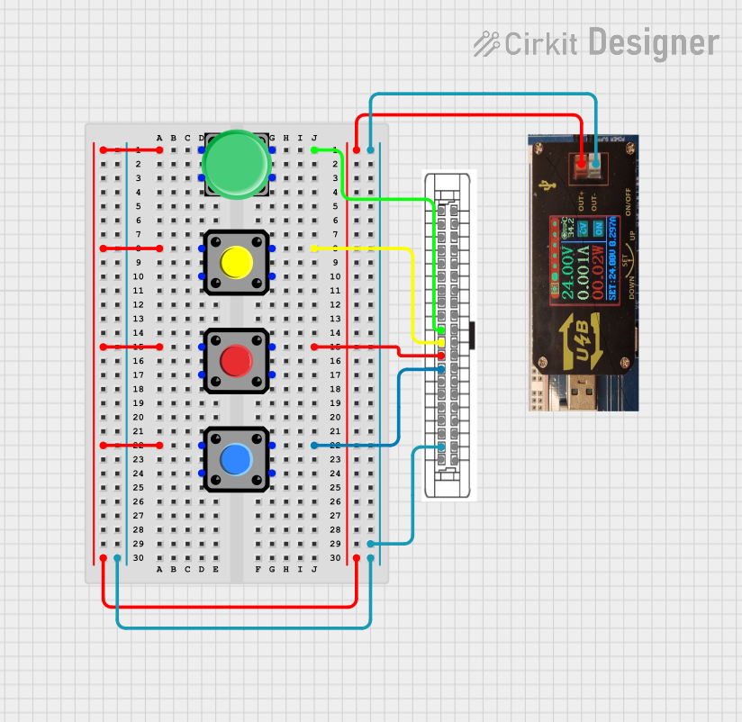 Open Project in Cirkit Designer
Explore Projects Built with Pushbutton_2P
Open Project in Cirkit DesignerOpen Project in Cirkit DesignerOpen Project in Cirkit DesignerOpen Project in Cirkit DesignerCommon Applications
- User interface buttons for electronic devices
- Reset or power switches in circuits
- Control of multiple circuits or functions in automation systems
- Prototyping and DIY electronics projects
Technical Specifications
The following table outlines the key technical details of the Pushbutton_2P:
| Parameter | Value |
|---|---|
| Manufacturer | Custom |
| Part ID | PushButton_2p |
| Number of Poles | 2 |
| Switch Type | Momentary (normally open) |
| Maximum Voltage Rating | 50V DC |
| Maximum Current Rating | 1A |
| Contact Resistance | ≤ 50 mΩ |
| Insulation Resistance | ≥ 100 MΩ at 500V DC |
| Operating Temperature | -20°C to +70°C |
| Mechanical Lifespan | 100,000 cycles |
Pin Configuration and Descriptions
The Pushbutton_2P has four pins, with two pins for each pole. The pin configuration is as follows:
| Pin Number | Description |
|---|---|
| 1 | Pole 1 - Normally Open (NO) Contact |
| 2 | Pole 1 - Common (COM) Contact |
| 3 | Pole 2 - Normally Open (NO) Contact |
| 4 | Pole 2 - Common (COM) Contact |
Usage Instructions
How to Use the Pushbutton_2P in a Circuit
- Identify the Pins: Refer to the pin configuration table to identify the NO and COM pins for each pole.
- Connect the Circuit:
- For each pole, connect the COM pin to the input or power source.
- Connect the NO pin to the load or circuit you wish to control.
- Operation: When the button is pressed, the NO pin will connect to the COM pin, completing the circuit. Releasing the button will break the connection.
Important Considerations
- Voltage and Current Ratings: Ensure the voltage and current in your circuit do not exceed the component's maximum ratings (50V DC, 1A).
- Debouncing: Pushbuttons can produce electrical noise (bouncing) when pressed or released. Use a debouncing circuit or software to ensure stable operation.
- Mounting: Secure the pushbutton in place to prevent mechanical stress on the pins.
Example: Using Pushbutton_2P with Arduino UNO
The following example demonstrates how to use the Pushbutton_2P to control an LED with an Arduino UNO. One pole of the pushbutton is used in this example.
Circuit Connections
- Connect Pin 2 (COM) of the pushbutton to GND on the Arduino.
- Connect Pin 1 (NO) of the pushbutton to Digital Pin 2 on the Arduino.
- Connect an LED to Digital Pin 13 with a 220Ω resistor in series.
Arduino Code
// Define pin numbers
const int buttonPin = 2;  // Pushbutton connected to digital pin 2
const int ledPin = 13;    // LED connected to digital pin 13

// Variable to store button state
int buttonState = 0;

void setup() {
  pinMode(buttonPin, INPUT_PULLUP); // Set button pin as input with internal pull-up
  pinMode(ledPin, OUTPUT);         // Set LED pin as output
}

void loop() {
  // Read the state of the pushbutton
  buttonState = digitalRead(buttonPin);

  // If button is pressed (LOW state due to pull-up resistor)
  if (buttonState == LOW) {
    digitalWrite(ledPin, HIGH); // Turn on the LED
  } else {
    digitalWrite(ledPin, LOW);  // Turn off the LED
  }
}
Notes
- The internal pull-up resistor is used to ensure the button pin is not left floating when the button is not pressed.
- Modify the code to use the second pole of the pushbutton for additional functionality if needed.
Troubleshooting and FAQs
Common Issues
Button Not Responding:
- Check the wiring and ensure the correct pins are connected.
- Verify that the voltage and current ratings are not exceeded.
LED Flickering When Button is Pressed:
- This is likely caused by switch bouncing. Add a debouncing circuit (e.g., an RC filter) or implement software debouncing in your code.
Button Feels Loose or Unstable:
- Ensure the pushbutton is securely mounted to the enclosure or breadboard.
Multiple Circuits Not Working Simultaneously:
- Verify the connections for both poles of the pushbutton. Ensure each pole is wired correctly.
FAQs
Q: Can I use the Pushbutton_2P to control AC circuits?
A: The Pushbutton_2P is rated for DC circuits up to 50V and 1A. It is not recommended for use in AC circuits unless the ratings are strictly adhered to.
Q: How do I debounce the pushbutton in software?
A: You can use a delay or a state-change detection algorithm in your code to filter out bouncing signals.
Q: Can I use both poles independently?
A: Yes, the two poles are electrically isolated and can be used to control two separate circuits or functions.
Q: What is the lifespan of the Pushbutton_2P?
A: The mechanical lifespan is rated at 100,000 cycles under normal operating conditions.