Cirkit Designer Logo
Cirkit Designer
Your all-in-one circuit design IDE
Home / 
Component Documentation

How to Use ARDUINO UNO R3 USB C 9V: Examples, Pinouts, and Specs

Image of ARDUINO UNO R3 USB C 9V
Cirkit Designer LogoDesign with ARDUINO UNO R3 USB C 9V in Cirkit Designer

Introduction

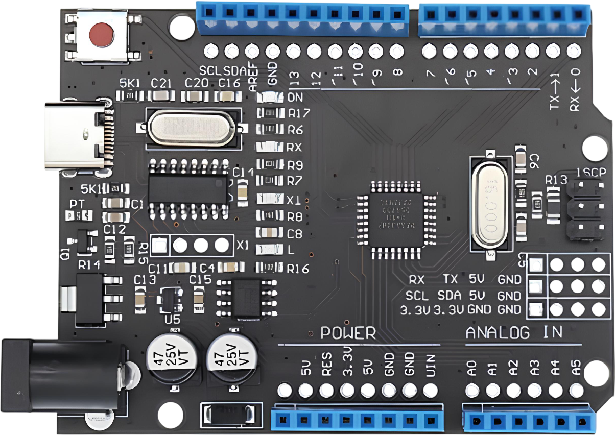
The Arduino UNO R3 USB C 9V is a microcontroller board developed by Arduino, designed for ease of use in a wide range of electronic projects. It is an updated version of the classic Arduino UNO R3, featuring a USB-C connector for modern connectivity and a 9V power input option for enhanced flexibility. This board is based on the ATmega328P microcontroller and is ideal for beginners and professionals alike, offering a robust platform for prototyping, learning, and developing embedded systems.

Explore Projects Built with ARDUINO UNO R3 USB C 9V

Use Cirkit Designer to design, explore, and prototype these projects online. Some projects support real-time simulation. Click "Open Project" to start designing instantly!
Arduino UNO Controlled Power Supply with 9V Battery and Step-Up Converter
Image of kkprojects: A project utilizing ARDUINO UNO R3 USB C 9V in a practical application
This circuit uses a 9V battery connected through a rocker switch to power an adjustable step-up voltage regulator, which in turn supplies power to an Arduino UNO microcontroller. The switch allows for manual power control, while the voltage regulator ensures the Arduino receives a stable and possibly higher voltage than the battery's nominal 9V. The Arduino UNO is programmed to perform user-defined tasks, but the provided code is empty, indicating that specific functionality is yet to be implemented.
Cirkit Designer LogoOpen Project in Cirkit Designer
Arduino UNO Powered Battery Circuit for Basic Control
Image of 14: A project utilizing ARDUINO UNO R3 USB C 9V in a practical application
This circuit consists of an Arduino UNO powered by a 9V battery, with the battery's positive terminal connected to the Arduino's Vin pin and the negative terminal connected to the GND pin. The Arduino is set up to run a basic program, which currently contains empty setup and loop functions, indicating that it is ready for further development.
Cirkit Designer LogoOpen Project in Cirkit Designer
Arduino UNO R4 WiFi Controlled Servo Motor with Diode Protection
Image of Arduino Uno Rev 4 Wifi (Servo Motor): A project utilizing ARDUINO UNO R3 USB C 9V in a practical application
This circuit features an Arduino UNO R4 WiFi microcontroller powered by a 9V battery, with its ground connected to the negative terminal of the battery. A servo motor (MG996R) is controlled by the Arduino through digital pin D9, and it is powered by a 4xAA battery pack through a 1N4007 rectifier diode for polarity protection. The provided code for the Arduino is a template with empty setup and loop functions, indicating that the specific control logic for the servo has not been implemented yet.
Cirkit Designer LogoOpen Project in Cirkit Designer
Arduino UNO Powered by 9V Battery
Image of Test project sharing: A project utilizing ARDUINO UNO R3 USB C 9V in a practical application
This circuit consists of an Arduino UNO microcontroller powered by a 9V battery. The battery's positive terminal is connected to the Arduino's Vin pin for power, and the negative terminal is connected to the Arduino's GND pin to complete the circuit. The provided code suggests that the Arduino is set up for a basic operation, but without specific functionality implemented in the loop or setup functions.
Cirkit Designer LogoOpen Project in Cirkit Designer

Explore Projects Built with ARDUINO UNO R3 USB C 9V

Use Cirkit Designer to design, explore, and prototype these projects online. Some projects support real-time simulation. Click "Open Project" to start designing instantly!
Image of kkprojects: A project utilizing ARDUINO UNO R3 USB C 9V in a practical application
Arduino UNO Controlled Power Supply with 9V Battery and Step-Up Converter
This circuit uses a 9V battery connected through a rocker switch to power an adjustable step-up voltage regulator, which in turn supplies power to an Arduino UNO microcontroller. The switch allows for manual power control, while the voltage regulator ensures the Arduino receives a stable and possibly higher voltage than the battery's nominal 9V. The Arduino UNO is programmed to perform user-defined tasks, but the provided code is empty, indicating that specific functionality is yet to be implemented.
Cirkit Designer LogoOpen Project in Cirkit Designer
Image of 14: A project utilizing ARDUINO UNO R3 USB C 9V in a practical application
Arduino UNO Powered Battery Circuit for Basic Control
This circuit consists of an Arduino UNO powered by a 9V battery, with the battery's positive terminal connected to the Arduino's Vin pin and the negative terminal connected to the GND pin. The Arduino is set up to run a basic program, which currently contains empty setup and loop functions, indicating that it is ready for further development.
Cirkit Designer LogoOpen Project in Cirkit Designer
Image of Arduino Uno Rev 4 Wifi (Servo Motor): A project utilizing ARDUINO UNO R3 USB C 9V in a practical application
Arduino UNO R4 WiFi Controlled Servo Motor with Diode Protection
This circuit features an Arduino UNO R4 WiFi microcontroller powered by a 9V battery, with its ground connected to the negative terminal of the battery. A servo motor (MG996R) is controlled by the Arduino through digital pin D9, and it is powered by a 4xAA battery pack through a 1N4007 rectifier diode for polarity protection. The provided code for the Arduino is a template with empty setup and loop functions, indicating that the specific control logic for the servo has not been implemented yet.
Cirkit Designer LogoOpen Project in Cirkit Designer
Image of Test project sharing: A project utilizing ARDUINO UNO R3 USB C 9V in a practical application
Arduino UNO Powered by 9V Battery
This circuit consists of an Arduino UNO microcontroller powered by a 9V battery. The battery's positive terminal is connected to the Arduino's Vin pin for power, and the negative terminal is connected to the Arduino's GND pin to complete the circuit. The provided code suggests that the Arduino is set up for a basic operation, but without specific functionality implemented in the loop or setup functions.
Cirkit Designer LogoOpen Project in Cirkit Designer

Common Applications and Use Cases

  • Prototyping and testing electronic circuits
  • IoT (Internet of Things) projects
  • Robotics and automation systems
  • Educational tools for learning programming and electronics
  • Sensor data acquisition and processing
  • Home automation and DIY projects

Technical Specifications

The Arduino UNO R3 USB C 9V retains the core features of the original UNO R3 while introducing modern enhancements. Below are the key technical details:

Key Technical Details

  • Microcontroller: ATmega328P
  • Operating Voltage: 5V
  • Input Voltage (recommended): 7-12V
  • Input Voltage (limit): 6-20V
  • Digital I/O Pins: 14 (6 provide PWM output)
  • Analog Input Pins: 6
  • DC Current per I/O Pin: 20 mA
  • Flash Memory: 32 KB (0.5 KB used by bootloader)
  • SRAM: 2 KB
  • EEPROM: 1 KB
  • Clock Speed: 16 MHz
  • USB Connector: USB-C
  • Power Connector: Barrel jack (9V input supported)
  • Dimensions: 68.6 mm x 53.4 mm
  • Weight: 25 g

Pin Configuration and Descriptions

The Arduino UNO R3 USB C 9V features a standard pin layout. Below is a detailed description of the pins:

Digital Pins

Pin Number Function Description
0 (RX) UART Receive Serial communication receive pin
1 (TX) UART Transmit Serial communication transmit pin
2-13 Digital I/O General-purpose digital input/output pins
3, 5, 6, 9, 10, 11 PWM Output Pulse-width modulation capable pins

Analog Pins

Pin Number Function Description
A0-A5 Analog Input Read analog signals (0-5V)

Power Pins

Pin Name Function Description
VIN Input Voltage External power input (7-12V recommended)
5V Regulated 5V Output Powers external components
3.3V Regulated 3.3V Output Powers low-voltage components
GND Ground Common ground for the circuit
IOREF I/O Reference Voltage Provides voltage reference for I/O pins
RESET Reset Resets the microcontroller

Usage Instructions

The Arduino UNO R3 USB C 9V is straightforward to use and compatible with the Arduino IDE. Follow these steps to get started:

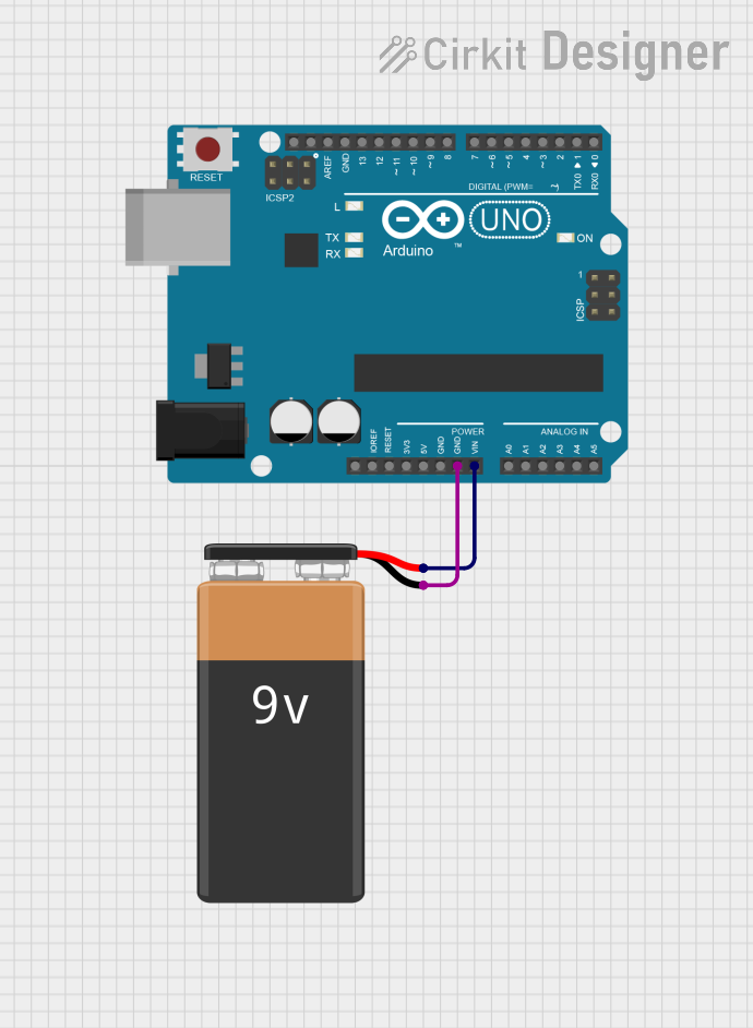
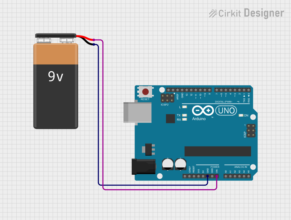
Step 1: Powering the Board

  • Connect the board to your computer using a USB-C cable for power and programming.
  • Alternatively, use a 9V DC adapter with the barrel jack for standalone operation.

Step 2: Installing the Arduino IDE

  • Download and install the Arduino IDE from the official Arduino website.
  • Ensure the correct drivers are installed for the USB-C interface.

Step 3: Writing and Uploading Code

  1. Open the Arduino IDE and select Tools > Board > Arduino UNO.
  2. Select the appropriate Port under the Tools menu.
  3. Write your code or use an example sketch.
  4. Click the Upload button to program the board.

Example Code: Blinking an LED

The following code demonstrates how to blink an LED connected to pin 13:

// This example code blinks the onboard LED connected to pin 13
// The LED will turn on for 1 second and off for 1 second repeatedly

void setup() {
  pinMode(13, OUTPUT); // Set pin 13 as an output
}

void loop() {
  digitalWrite(13, HIGH); // Turn the LED on
  delay(1000);            // Wait for 1 second
  digitalWrite(13, LOW);  // Turn the LED off
  delay(1000);            // Wait for 1 second
}

Important Considerations and Best Practices

  • Avoid exceeding the maximum current rating (20 mA) for I/O pins to prevent damage.
  • Use external pull-up or pull-down resistors for stable digital input signals.
  • Ensure proper grounding when interfacing with external components.
  • Use a regulated power supply to avoid voltage fluctuations.

Troubleshooting and FAQs

Common Issues and Solutions

  1. Board Not Detected by Computer

    • Ensure the USB-C cable is data-capable (not just a charging cable).
    • Check that the correct drivers are installed for the Arduino UNO R3 USB C.
  2. Code Upload Fails

    • Verify the correct board and port are selected in the Arduino IDE.
    • Press the RESET button on the board before uploading.
  3. LED Not Blinking

    • Confirm the LED is connected to the correct pin (pin 13 in the example).
    • Check for loose connections or damaged components.
  4. Power Issues

    • Ensure the input voltage is within the recommended range (7-12V).
    • Check the power source and connections.

FAQs

  • Q: Can I power the board using both USB-C and the barrel jack simultaneously?
    A: Yes, but the board will prioritize the external power source (barrel jack) if both are connected.

  • Q: Is the Arduino UNO R3 USB C 9V compatible with shields designed for the original UNO R3?
    A: Yes, it maintains the same form factor and pin layout as the original UNO R3.

  • Q: Can I use the board for 3.3V logic components?
    A: Yes, the board provides a 3.3V output pin for powering low-voltage components.

By following this documentation, you can effectively utilize the Arduino UNO R3 USB C 9V for your projects.