How to Use Adafruit 2.13in eInk Under FeatherWing: Examples, Pinouts, and Specs
Introduction
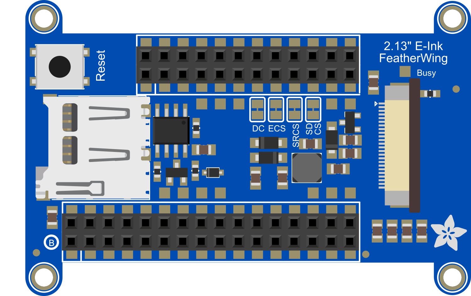
The Adafruit 2.13in eInk Under FeatherWing is an electronic paper display module that provides a low-power, high-contrast, and sunlight-readable display solution for your projects. This eInk display is specifically designed to interface seamlessly with the Adafruit Feather series of development boards. It is ideal for applications where a power-efficient and readable display is crucial, such as wearable devices, e-readers, and IoT devices.
Explore Projects Built with Adafruit 2.13in eInk Under FeatherWing
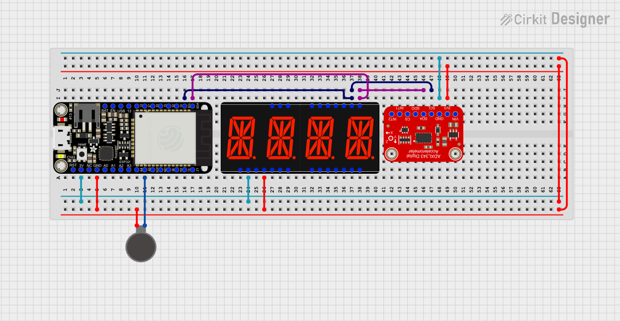
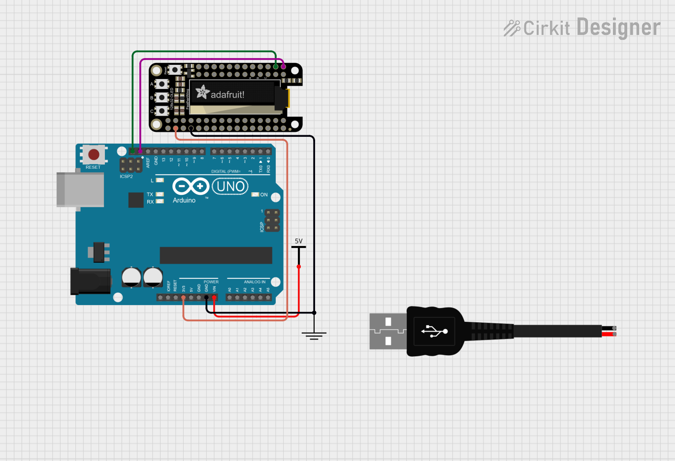
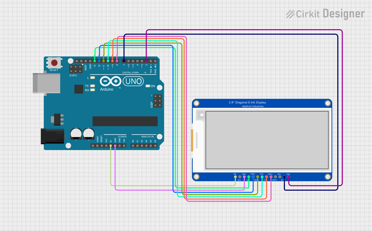
Explore Projects Built with Adafruit 2.13in eInk Under FeatherWing
Common Applications and Use Cases
- Wearable technology
- Portable e-readers
- Digital signage
- IoT devices with display requirements
- Battery-powered sensor displays
Technical Specifications
Key Technical Details
- Display Size: 2.13 inches diagonal
- Resolution: 250x122 pixels
- Grayscale Levels: 2-bit (4 gray levels)
- Interface: SPI
- Operating Voltage: 3.3V (from Feather board)
- Dimensions: 51mm x 22.8mm x 7mm
Pin Configuration and Descriptions
| Pin | Description |
|---|---|
| GND | Ground |
| 3V3 | 3.3V Power Supply |
| BUSY | Busy State Output |
| RST | Reset Pin |
| DC | Data/Command Control Pin |
| CS | Chip Select for SPI |
| SCK | SPI Clock |
| MOSI | SPI Master Out Slave In |
| MISO | SPI Master In Slave Out (Not used) |
Usage Instructions
How to Use the Component in a Circuit
- Mounting: Secure the eInk FeatherWing underneath your Adafruit Feather board using the provided headers.
- Wiring: Ensure that the SPI and control pins are properly connected to the corresponding pins on the Feather board.
- Power: The display is powered through the 3.3V pin from the Feather board.
Important Considerations and Best Practices
- SPI Communication: The display uses SPI for data transfer. Ensure that the SPI pins are not shared with other peripherals unless they are designed to be shared.
- Partial Refresh: To avoid ghosting and to prolong the life of the display, use partial refreshes when possible.
- Power Cycling: Properly power cycle the display by toggling the reset pin if the display becomes unresponsive.
- Library Use: Utilize Adafruit's provided libraries for interfacing with the display to simplify development.
Example Code for Arduino UNO
Below is an example code snippet for initializing and displaying text on the Adafruit 2.13in eInk Under FeatherWing using an Arduino UNO. Ensure you have installed the Adafruit GFX and eInk libraries.
#include <Adafruit_GFX.h>
#include <Adafruit_EPD.h>

#define EPD_CS     10
#define EPD_DC     9
#define EPD_RESET  8
#define EPD_BUSY   7

// Create an instance of the display
Adafruit_SSD1675 display = Adafruit_SSD1675(250, 122, EPD_CS, EPD_DC, EPD_RESET, EPD_BUSY);

void setup() {
  display.begin(); // Initialize the display
  display.clearBuffer(); // Clear the buffer to start
  display.setTextSize(1); // Set the text size
  display.setTextColor(EPD_BLACK); // Set the text color
  display.setCursor(0,0); // Set the cursor position
  display.print("Hello, eInk!"); // Print text to the buffer
  display.display(); // Display what's in the buffer
}

void loop() {
  // Nothing to do here
}
Troubleshooting and FAQs
Common Issues Users Might Face
- Display Not Updating: Ensure that the display is correctly powered and that the SPI connections are secure.
- Ghosting: If ghosting occurs, increase the frequency of full refreshes or adjust the partial refresh settings.
- Unresponsive Display: Check the reset pin and power cycle the display.
Solutions and Tips for Troubleshooting
- SPI Issues: Verify that other SPI devices are not interfering with the display's operation.
- Library Updates: Make sure you have the latest version of the Adafruit GFX and eInk libraries.
- Power Supply: Confirm that the 3.3V power supply from the Feather board is stable and within the required range.
FAQs
Q: Can the display show images? A: Yes, the display can show images in 2-bit grayscale.
Q: Is the display compatible with all Feather boards? A: It is designed to be compatible with boards that follow the Feather specification. Check the pin compatibility for non-Adafruit boards.
Q: How do I update the display content?
A: Use the display library's functions to write to the buffer and then call display.display() to update the screen.
Q: Can I use the display with a 5V logic microcontroller? A: No, the display is designed for 3.3V logic. Using it with 5V logic may damage the display.
For further assistance, consult the Adafruit forums or the product's official documentation.