How to Use sparkfun heart rate monitor and pulse oximeter: Examples, Pinouts, and Specs
Introduction
The SparkFun Heart Rate Monitor and Pulse Oximeter is a compact sensor module designed to measure heart rate and blood oxygen levels using photoplethysmography (PPG) technology. This module is ideal for health monitoring applications, including fitness tracking, medical devices, and wearable technology. Its small size and ease of integration make it a popular choice for both hobbyists and professionals.
Common applications and use cases:
- Fitness trackers and smartwatches
- Health monitoring systems
- Biomedical research projects
- DIY electronics and Arduino-based projects
Explore Projects Built with sparkfun heart rate monitor and pulse oximeter
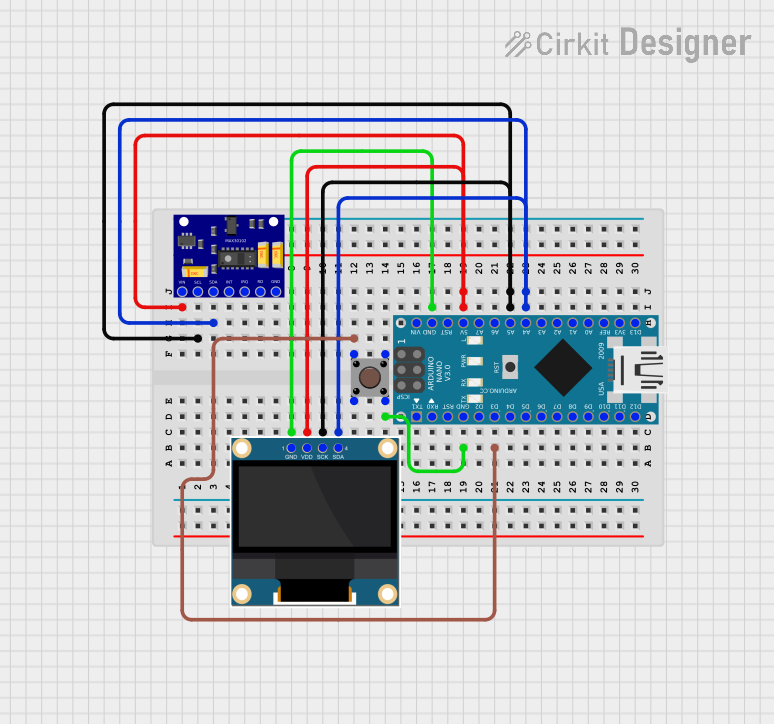
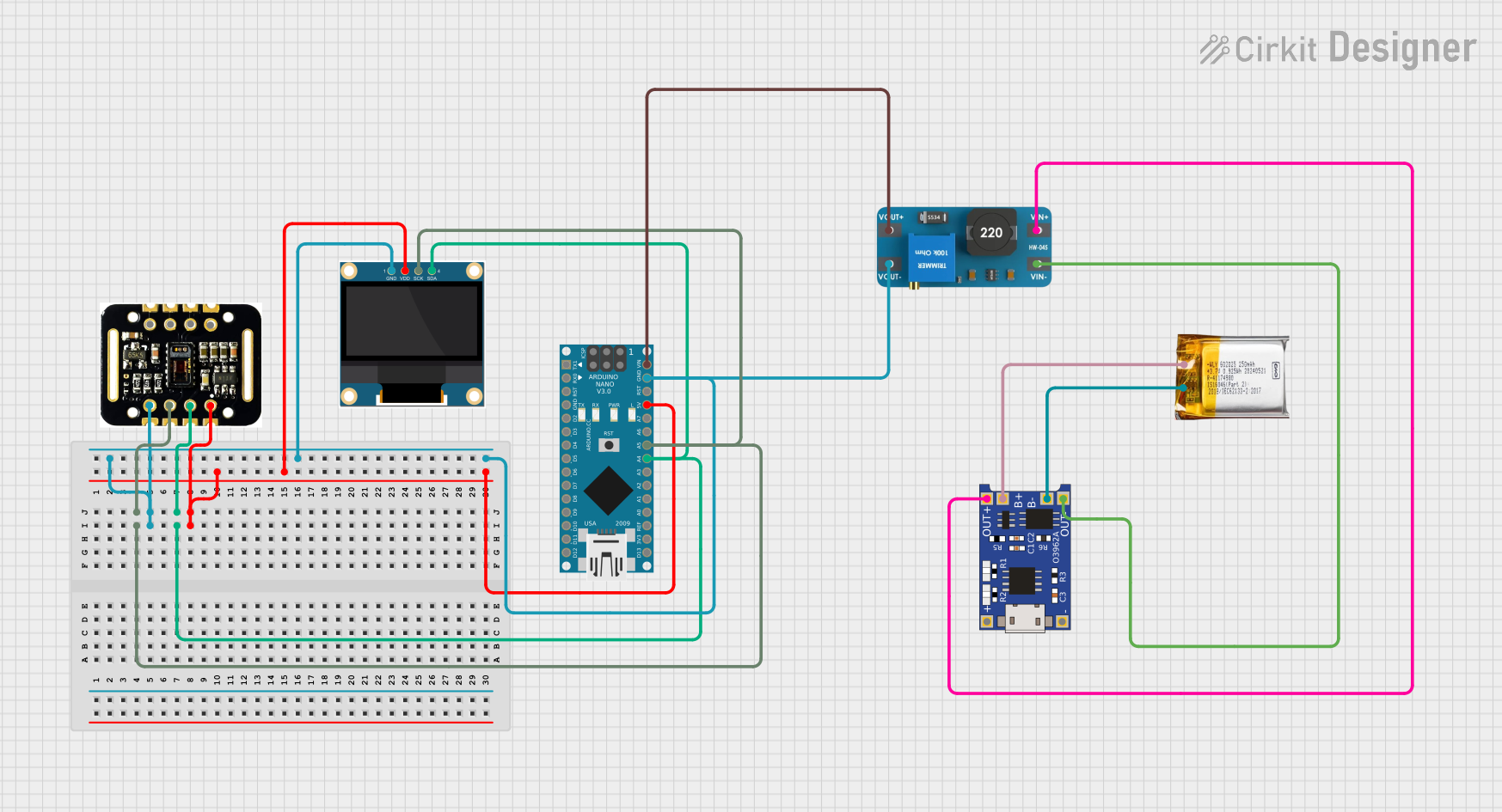
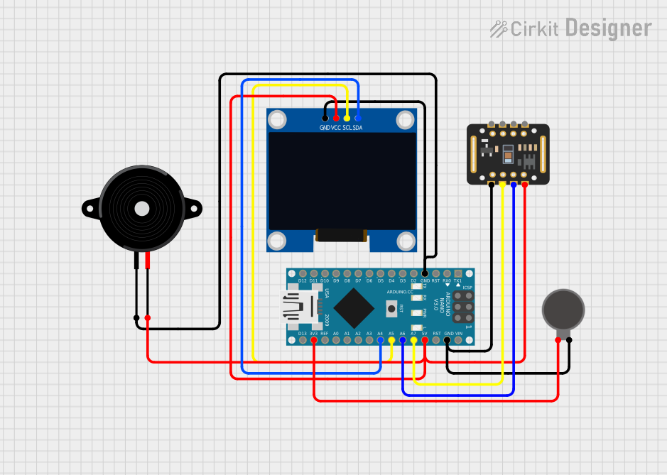

Explore Projects Built with sparkfun heart rate monitor and pulse oximeter
Technical Specifications
- Sensor Type: Photoplethysmography (PPG)
- Operating Voltage: 1.8V to 3.3V
- Current Consumption: ~5mA (typical)
- Communication Protocol: I2C
- I2C Address: 0x57 (default)
- Measurement Parameters: Heart rate (BPM), SpO2 (blood oxygen saturation)
- Operating Temperature: -40°C to +85°C
- Dimensions: 1.0" x 0.5" (25.4mm x 12.7mm)
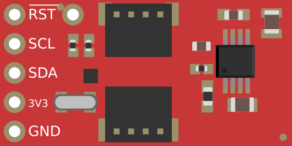
Pin Configuration and Descriptions
| Pin | Name | Description |
|---|---|---|
| 1 | VIN | Power supply input (1.8V to 3.3V). Connect to the 3.3V pin of your microcontroller. |
| 2 | GND | Ground connection. Connect to the ground of your circuit. |
| 3 | SDA | I2C data line. Connect to the SDA pin of your microcontroller. |
| 4 | SCL | I2C clock line. Connect to the SCL pin of your microcontroller. |
| 5 | INT | Interrupt pin. Can be used to signal data availability (optional). |
Usage Instructions
How to Use the Component in a Circuit
- Power the Module: Connect the VIN pin to a 3.3V power source and the GND pin to ground.
- Connect I2C Lines: Connect the SDA and SCL pins to the corresponding I2C pins on your microcontroller.
- Optional Interrupt: If desired, connect the INT pin to a GPIO pin on your microcontroller to handle interrupts.
- Pull-Up Resistors: Ensure that the I2C lines (SDA and SCL) have appropriate pull-up resistors (typically 4.7kΩ to 10kΩ).
Important Considerations and Best Practices
- Power Supply: Ensure the module is powered with a stable 3.3V source. Exceeding the voltage range may damage the sensor.
- I2C Address Conflicts: If using multiple I2C devices, ensure there are no address conflicts. The default address for this module is 0x57.
- Ambient Light: Minimize ambient light interference by enclosing the sensor in a dark environment or using it in low-light conditions.
- Skin Contact: For accurate readings, ensure the sensor is in direct contact with the skin, preferably on a fingertip or earlobe.
Example Code for Arduino UNO
Below is an example of how to interface the SparkFun Heart Rate Monitor and Pulse Oximeter with an Arduino UNO using the I2C protocol.
#include <Wire.h> // Include the Wire library for I2C communication
#include "MAX30102.h" // Include the library for the MAX30102 sensor

MAX30102 sensor; // Create an instance of the MAX30102 class

void setup() {
  Serial.begin(9600); // Initialize serial communication at 9600 baud
  Wire.begin(); // Initialize I2C communication

  // Initialize the MAX30102 sensor
  if (!sensor.begin()) {
    Serial.println("MAX30102 initialization failed!");
    while (1); // Halt the program if initialization fails
  }
  Serial.println("MAX30102 initialized successfully!");
}

void loop() {
  // Variables to store heart rate and SpO2 readings
  int heartRate;
  float spo2;

  // Read data from the sensor
  if (sensor.check() == true) {
    heartRate = sensor.getHeartRate(); // Get heart rate in BPM
    spo2 = sensor.getSpO2(); // Get blood oxygen saturation percentage

    // Print the readings to the Serial Monitor
    Serial.print("Heart Rate: ");
    Serial.print(heartRate);
    Serial.print(" BPM, SpO2: ");
    Serial.print(spo2);
    Serial.println(" %");
  } else {
    Serial.println("Sensor data not available.");
  }

  delay(1000); // Wait for 1 second before the next reading
}
Note: The above code assumes you have installed the MAX30102 library. You can install it via the Arduino Library Manager.
Troubleshooting and FAQs
Common Issues and Solutions
No Data from the Sensor:
- Ensure the sensor is properly connected to the microcontroller.
- Verify that the I2C address (0x57) matches the address in your code.
- Check for loose or incorrect wiring.
Inaccurate Readings:
- Ensure the sensor is in direct contact with the skin.
- Minimize ambient light interference by shielding the sensor.
- Verify that the power supply voltage is stable and within the specified range.
I2C Communication Errors:
- Check the pull-up resistors on the SDA and SCL lines.
- Ensure the I2C clock speed is compatible with the sensor (typically 100kHz or 400kHz).
FAQs
Q: Can this module be powered with 5V?
A: No, the module operates within a voltage range of 1.8V to 3.3V. Using 5V may damage the sensor.
Q: How do I improve the accuracy of the readings?
A: Ensure proper skin contact, minimize motion during measurements, and reduce ambient light interference.
Q: Can I use this module with a Raspberry Pi?
A: Yes, the module communicates via I2C, which is supported by the Raspberry Pi. Ensure proper voltage level shifting if needed.
Q: What is the typical range for SpO2 readings?
A: Healthy individuals typically have SpO2 levels between 95% and 100%. Lower values may indicate health issues.
Q: Is this module suitable for medical-grade applications?
A: No, this module is intended for educational and hobbyist purposes. It is not certified for medical use.