
How to Use Buck Converter: Examples, Pinouts, and Specs
 Design with Buck Converter in Cirkit Designer
Introduction
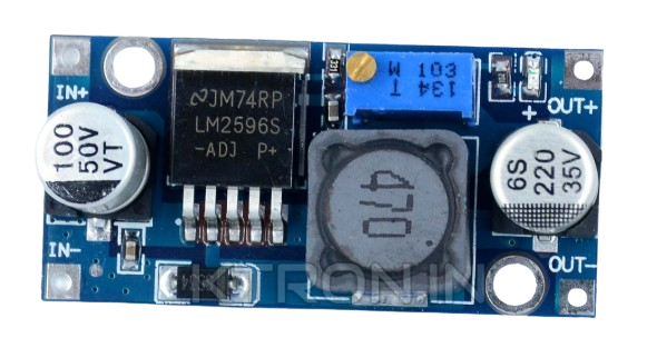
The Buck Converter (LM2596S), manufactured by Sharvi Technologies (OPC) Pvt. Ltd., is a DC-DC power converter designed to step down voltage efficiently while stepping up current. It achieves this by utilizing a switching element, a diode, an inductor, and a capacitor. This component is widely used in applications requiring regulated lower voltage from a higher voltage source.
Explore Projects Built with Buck Converter
 Open Project in Cirkit Designer
 Open Project in Cirkit Designer
 Open Project in Cirkit Designer
 Open Project in Cirkit Designer
Explore Projects Built with Buck Converter
Open Project in Cirkit DesignerOpen Project in Cirkit DesignerOpen Project in Cirkit DesignerOpen Project in Cirkit DesignerCommon Applications and Use Cases
- Powering microcontrollers and sensors from higher voltage sources
- Battery-powered devices requiring efficient voltage regulation
- LED drivers and lighting systems
- Industrial automation and control systems
- Consumer electronics such as chargers and adapters
Technical Specifications
The LM2596S Buck Converter is a highly efficient and versatile component. Below are its key technical details:
Key Technical Details
| Parameter | Value |
|---|---|
| Input Voltage Range | 4.5V to 40V |
| Output Voltage Range | 1.23V to 37V (adjustable) |
| Output Current | Up to 3A |
| Efficiency | Up to 92% |
| Switching Frequency | 150 kHz |
| Operating Temperature | -40°C to +125°C |
| Package Type | TO-220 |
Pin Configuration and Descriptions
The LM2596S has a 5-pin configuration. Below is the pinout and description:
| Pin Number | Pin Name | Description |
|---|---|---|
| 1 | VIN | Input voltage pin. Connect to the unregulated DC input voltage. |
| 2 | Output | Regulated DC output voltage. Connect to the load. |
| 3 | Ground | Ground pin. Connect to the circuit ground. |
| 4 | Feedback | Feedback pin. Used to set the output voltage via an external resistor divider. |
| 5 | ON/OFF | Enable pin. Logic high enables the converter; logic low disables it. |
Usage Instructions
The LM2596S Buck Converter is straightforward to use in a circuit. Follow the steps below to integrate it effectively:
Step-by-Step Instructions
- Input Voltage Connection: Connect the input voltage (VIN) to the input pin. Ensure the input voltage is within the range of 4.5V to 40V.
- Output Voltage Adjustment: Use a resistor divider network connected to the Feedback pin to set the desired output voltage. The formula for output voltage is: [ V_{OUT} = V_{REF} \times \left(1 + \frac{R1}{R2}\right) ] where ( V_{REF} ) is 1.23V.
- Output Connection: Connect the load to the Output pin. Ensure the load does not exceed the maximum current rating of 3A.
- Enable/Disable Control: Use the ON/OFF pin to enable or disable the converter. Leave it unconnected or pull it high to enable the converter.
- Capacitor and Inductor Selection: Select appropriate capacitors and inductors based on the input and output voltage requirements for stable operation.
Important Considerations and Best Practices
- Use low Equivalent Series Resistance (ESR) capacitors for better performance.
- Ensure proper heat dissipation by using a heatsink if the converter operates at high currents.
- Place the input and output capacitors as close to the pins as possible to minimize noise.
- Avoid exceeding the maximum input voltage and output current ratings to prevent damage.
Example: Connecting to an Arduino UNO
The LM2596S can be used to power an Arduino UNO from a higher voltage source. Below is an example circuit and code:
Circuit
- Connect the input of the LM2596S to a 12V DC power supply.
- Adjust the output voltage to 5V using the feedback resistor divider.
- Connect the output of the LM2596S to the 5V pin of the Arduino UNO.
Code
// Example code for Arduino UNO powered by LM2596S Buck Converter
// This code blinks an LED connected to pin 13

void setup() {
  pinMode(13, OUTPUT); // Set pin 13 as an output
}

void loop() {
  digitalWrite(13, HIGH); // Turn the LED on
  delay(1000);            // Wait for 1 second
  digitalWrite(13, LOW);  // Turn the LED off
  delay(1000);            // Wait for 1 second
}
Troubleshooting and FAQs
Common Issues and Solutions
| Issue | Possible Cause | Solution |
|---|---|---|
| No output voltage | Input voltage not connected or too low | Check the input voltage and ensure it is within range. |
| Output voltage unstable | Incorrect capacitor or inductor values | Use recommended values for capacitors and inductors. |
| Overheating | Excessive load current or poor ventilation | Reduce the load current or add a heatsink. |
| Output voltage not adjustable | Incorrect feedback resistor configuration | Verify the resistor divider network. |
FAQs
Can the LM2596S handle AC input?
No, the LM2596S requires a DC input voltage. Use a rectifier and filter circuit to convert AC to DC before connecting.What is the maximum efficiency of the LM2596S?
The LM2596S can achieve up to 92% efficiency under optimal conditions.Can I use the LM2596S for battery charging?
Yes, but ensure the output voltage and current are configured appropriately for the battery type.How do I calculate the inductor value?
The inductor value depends on the input voltage, output voltage, and switching frequency. Refer to the datasheet for detailed calculations.
By following this documentation, you can effectively integrate the LM2596S Buck Converter into your projects for efficient voltage regulation.