How to Use 4x3 Keypad: Examples, Pinouts, and Specs
Introduction
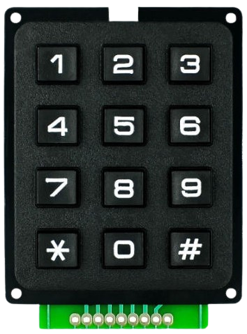
A 4x3 keypad is a matrix keypad consisting of 12 buttons arranged in 4 rows and 3 columns. It is widely used for user input in electronic devices due to its compact design and ease of integration. The keypad allows for efficient data entry and control, making it ideal for applications such as security systems (e.g., PIN entry), home appliances, and microcontroller-based projects like Arduino or Raspberry Pi systems.
Explore Projects Built with 4x3 Keypad


Explore Projects Built with 4x3 Keypad
Technical Specifications
- Number of Buttons: 12 (4 rows × 3 columns)
- Operating Voltage: 3.3V to 5V
- Current Consumption: Typically < 10mA
- Button Type: Momentary push buttons
- Interface: Matrix (row-column scanning)
- Dimensions: Varies by manufacturer, typically around 70mm × 50mm
- Connector Type: 7-pin header (4 row pins + 3 column pins)
Pin Configuration and Descriptions
The 4x3 keypad has 7 pins, which correspond to the rows and columns of the matrix. Below is the pinout:
| Pin | Label | Description |
|---|---|---|
| 1 | R1 | Row 1 |
| 2 | R2 | Row 2 |
| 3 | R3 | Row 3 |
| 4 | R4 | Row 4 |
| 5 | C1 | Column 1 |
| 6 | C2 | Column 2 |
| 7 | C3 | Column 3 |
Usage Instructions
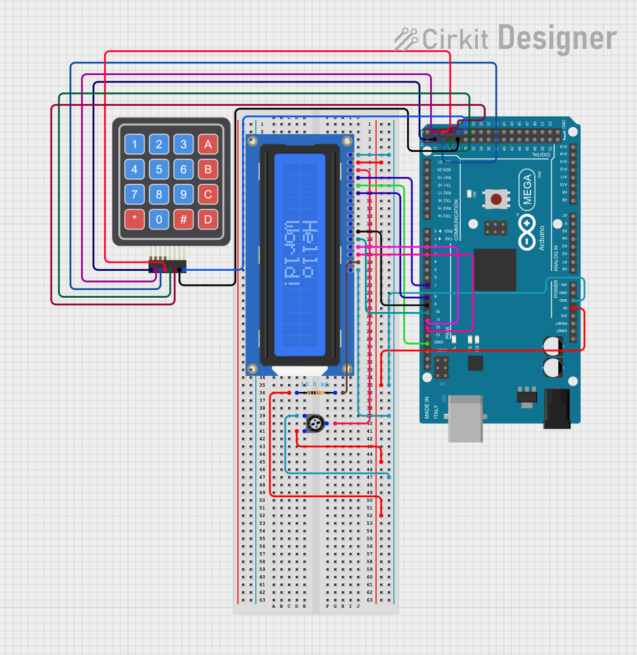
How to Use the 4x3 Keypad in a Circuit
Wiring the Keypad:
- Connect the 7 pins of the keypad to your microcontroller or development board.
- Assign the row pins (R1–R4) to digital input/output pins on the microcontroller.
- Assign the column pins (C1–C3) to additional digital input/output pins.
Matrix Scanning:
- The keypad works by scanning the rows and columns to detect which button is pressed.
- When a button is pressed, it connects a specific row to a specific column, allowing the microcontroller to identify the button.
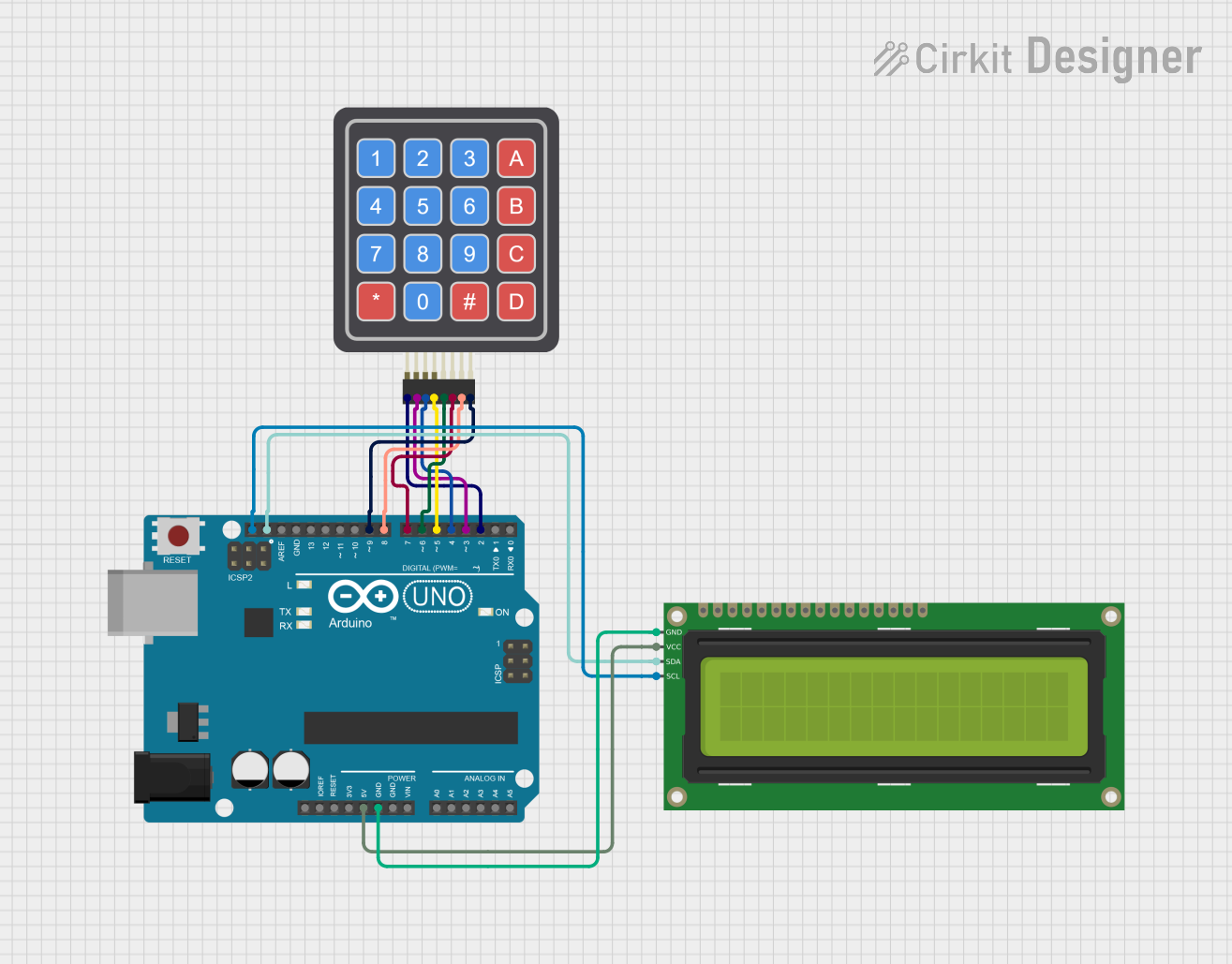
Using with Arduino:
- The Arduino Keypad library simplifies the process of interfacing with the keypad.
- Install the library via the Arduino IDE Library Manager (
Keypad by Mark Stanley and Alexander Brevig).
Example Arduino Code
Below is an example of how to use a 4x3 keypad with an Arduino UNO:
#include <Keypad.h>

// Define the rows and columns of the keypad
const byte ROWS = 4; // Four rows
const byte COLS = 3; // Three columns

// Define the keymap for the keypad
char keys[ROWS][COLS] = {
  {'1', '2', '3'},
  {'4', '5', '6'},
  {'7', '8', '9'},
  {'*', '0', '#'}
};

// Define the row and column pins connected to the Arduino
byte rowPins[ROWS] = {9, 8, 7, 6}; // Connect to R1, R2, R3, R4
byte colPins[COLS] = {5, 4, 3};    // Connect to C1, C2, C3

// Create the Keypad object
Keypad keypad = Keypad(makeKeymap(keys), rowPins, colPins, ROWS, COLS);

void setup() {
  Serial.begin(9600); // Initialize serial communication
  Serial.println("4x3 Keypad Test");
}

void loop() {
  char key = keypad.getKey(); // Check if a key is pressed

  if (key) {
    // Print the pressed key to the Serial Monitor
    Serial.print("Key Pressed: ");
    Serial.println(key);
  }
}
Important Considerations and Best Practices
- Debouncing: The keypad library handles debouncing, but if you are implementing your own code, ensure you account for it to avoid false readings.
- Pull-up Resistors: Internal pull-up resistors can be enabled on the microcontroller pins to ensure stable readings.
- Power Supply: Ensure the keypad operates within its voltage range (3.3V–5V) to avoid damage.
- Secure Mounting: For long-term use, securely mount the keypad to prevent mechanical stress on the pins.
Troubleshooting and FAQs
Common Issues and Solutions
No Key Press Detected:
- Verify the wiring between the keypad and the microcontroller.
- Check that the correct pins are defined in the code.
Incorrect Key Press Detected:
- Ensure the keymap in the code matches the physical layout of the keypad.
- Check for loose or shorted connections.
Multiple Keys Detected Simultaneously:
- This may occur due to electrical noise or poor debouncing. Use the Keypad library to handle debouncing effectively.
Keypad Not Responding:
- Confirm that the microcontroller pins are configured as input/output as required.
- Test the keypad with a multimeter to ensure all buttons are functional.
FAQs
Q: Can I use the 4x3 keypad with a 3.3V microcontroller?
A: Yes, the keypad is compatible with 3.3V systems. Ensure the microcontroller pins are configured correctly.
Q: How do I extend the keypad cable for larger projects?
A: Use shielded cables to reduce noise and interference. Keep the cable length as short as possible for reliable operation.
Q: Can I use the keypad for multiple simultaneous key presses?
A: The 4x3 keypad is not designed for multi-key detection. It is best suited for single key presses at a time.
Q: Is the keypad waterproof?
A: Most 4x3 keypads are not waterproof. For outdoor or wet environments, use a sealed or membrane keypad.
By following this documentation, you can effectively integrate and troubleshoot a 4x3 keypad in your electronic projects.