How to Use jJQ6500: Examples, Pinouts, and Specs
Introduction
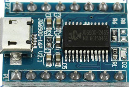
The jJQ6500 is a low-power audio playback module designed for embedded systems. It supports various audio formats, including MP3 and WAV, making it ideal for applications requiring sound effects or music playback. The module is compact, easy to integrate, and features a straightforward interface for control. It is commonly used in projects such as interactive displays, toys, alarms, and voice prompts.
Explore Projects Built with jJQ6500


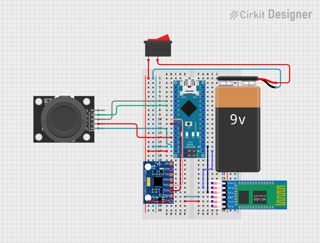
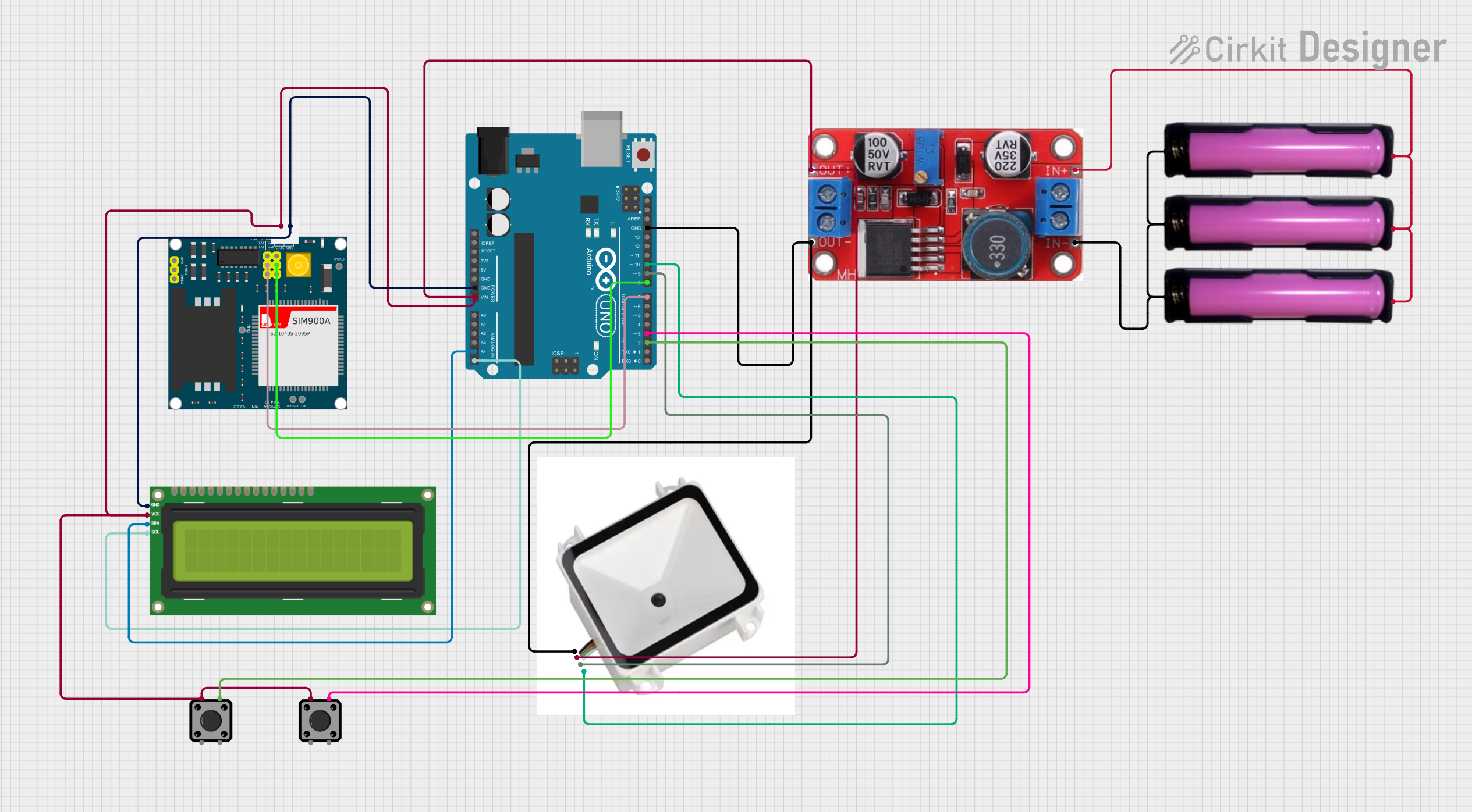
Explore Projects Built with jJQ6500
Common Applications
- Interactive kiosks and displays
- Toys and educational devices
- Alarm systems with voice prompts
- Audio playback in IoT devices
- Custom sound effects for embedded systems
Technical Specifications
The jJQ6500 module is designed for efficient audio playback with minimal power consumption. Below are its key technical details:
Key Specifications
| Parameter | Value |
|---|---|
| Operating Voltage | 3.3V to 5V |
| Operating Current | 20mA to 30mA |
| Audio Formats Supported | MP3, WAV |
| Storage Options | Built-in flash (up to 8MB) or |
| external microSD card | |
| Communication Protocols | UART, GPIO |
| Audio Output | Mono (DAC output) or stereo |
| (via external amplifier) | |
| Dimensions | 20mm x 15mm |
Pin Configuration
The jJQ6500 module has a simple pinout for easy integration. Below is the pin configuration:
| Pin Number | Pin Name | Description |
|---|---|---|
| 1 | VCC | Power supply input (3.3V to 5V) |
| 2 | GND | Ground connection |
| 3 | TX | UART transmit pin for communication |
| 4 | RX | UART receive pin for communication |
| 5 | IO1 | GPIO pin 1 for playback control (e.g., play specific tracks) |
| 6 | IO2 | GPIO pin 2 for playback control |
| 7 | DAC_R | Right channel DAC output (for external amplifier or speaker connection) |
| 8 | DAC_L | Left channel DAC output (for external amplifier or speaker connection) |
Usage Instructions
The jJQ6500 module is straightforward to use in a circuit. It can be controlled via UART commands or GPIO pins for basic playback functionality.
Connecting the jJQ6500 to a Circuit
- Power Supply: Connect the
VCCpin to a 3.3V or 5V power source and theGNDpin to ground. - Audio Output: Use the
DAC_RandDAC_Lpins to connect to an external amplifier or speaker. - Control:
- For UART control, connect the
TXandRXpins to a microcontroller (e.g., Arduino). - For GPIO control, use
IO1andIO2to trigger specific playback functions.
- For UART control, connect the
Example: Using jJQ6500 with Arduino UNO
Below is an example of how to control the jJQ6500 module using an Arduino UNO via UART:
Circuit Connections
- Connect
VCCto the Arduino's 5V pin. - Connect
GNDto the Arduino's GND pin. - Connect the
RXpin of the jJQ6500 to the Arduino's TX pin (pin 1). - Connect the
TXpin of the jJQ6500 to the Arduino's RX pin (pin 0).
Arduino Code Example
#include <SoftwareSerial.h>

// Define RX and TX pins for SoftwareSerial
SoftwareSerial audioSerial(10, 11); // RX = pin 10, TX = pin 11

void setup() {
  // Initialize serial communication with the jJQ6500 module
  audioSerial.begin(9600);
  Serial.begin(9600); // For debugging

  // Play the first track on the module
  playTrack(1);
}

void loop() {
  // Add your main code here
}

// Function to play a specific track
void playTrack(int trackNumber) {
  audioSerial.write(0x7E); // Start byte
  audioSerial.write(0x03); // Command length
  audioSerial.write(0xA0); // Play track command
  audioSerial.write(trackNumber); // Track number (1-based index)
  audioSerial.write(0x7E); // End byte

  Serial.print("Playing track: ");
  Serial.println(trackNumber);
}
Important Considerations
- Ensure the power supply voltage is within the specified range (3.3V to 5V).
- Use a decoupling capacitor (e.g., 10µF) near the power pins to reduce noise.
- If using an external microSD card, format it as FAT32 and ensure the audio files are named sequentially (e.g.,
001.mp3,002.mp3). - Avoid connecting the module's
TXpin directly to a 5V microcontroller's RX pin without a voltage divider or level shifter.
Troubleshooting and FAQs
Common Issues and Solutions
No Sound Output
- Cause: Incorrect wiring or missing audio files.
- Solution: Verify the connections to the
DAC_RandDAC_Lpins. Ensure the audio files are correctly formatted and stored on the microSD card or internal flash.
Module Not Responding to Commands
- Cause: Incorrect UART baud rate or wiring.
- Solution: Ensure the UART baud rate is set to 9600. Double-check the
TXandRXconnections.
Distorted Audio
- Cause: Insufficient power supply or incorrect audio output connections.
- Solution: Use a stable power source and ensure proper connections to the amplifier or speaker.
MicroSD Card Not Detected
- Cause: Improper formatting or incompatible card.
- Solution: Format the card as FAT32 and ensure it is within the supported size range (typically up to 32GB).
FAQs
Q: Can the jJQ6500 play audio files directly from its internal flash?
A: Yes, the module can store and play audio files from its built-in flash memory (up to 8MB).
Q: What is the maximum number of tracks the module can handle?
A: The module can handle up to 255 tracks, provided they are named sequentially.
Q: Can I control the volume of the audio playback?
A: Yes, volume control commands can be sent via UART to adjust the playback volume.
Q: Is the module compatible with 3.3V microcontrollers?
A: Yes, the jJQ6500 is compatible with both 3.3V and 5V logic levels.