How to Use Tb6600 4.5amps : Examples, Pinouts, and Specs
Introduction
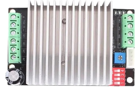
The TB6600 is a high-performance stepper motor driver capable of handling up to 4.5 amps of current. It is widely used in CNC machines, 3D printers, and other applications requiring precise motor control. This driver is known for its reliability and ease of use, making it a popular choice among hobbyists and professionals alike.
Explore Projects Built with Tb6600 4.5amps

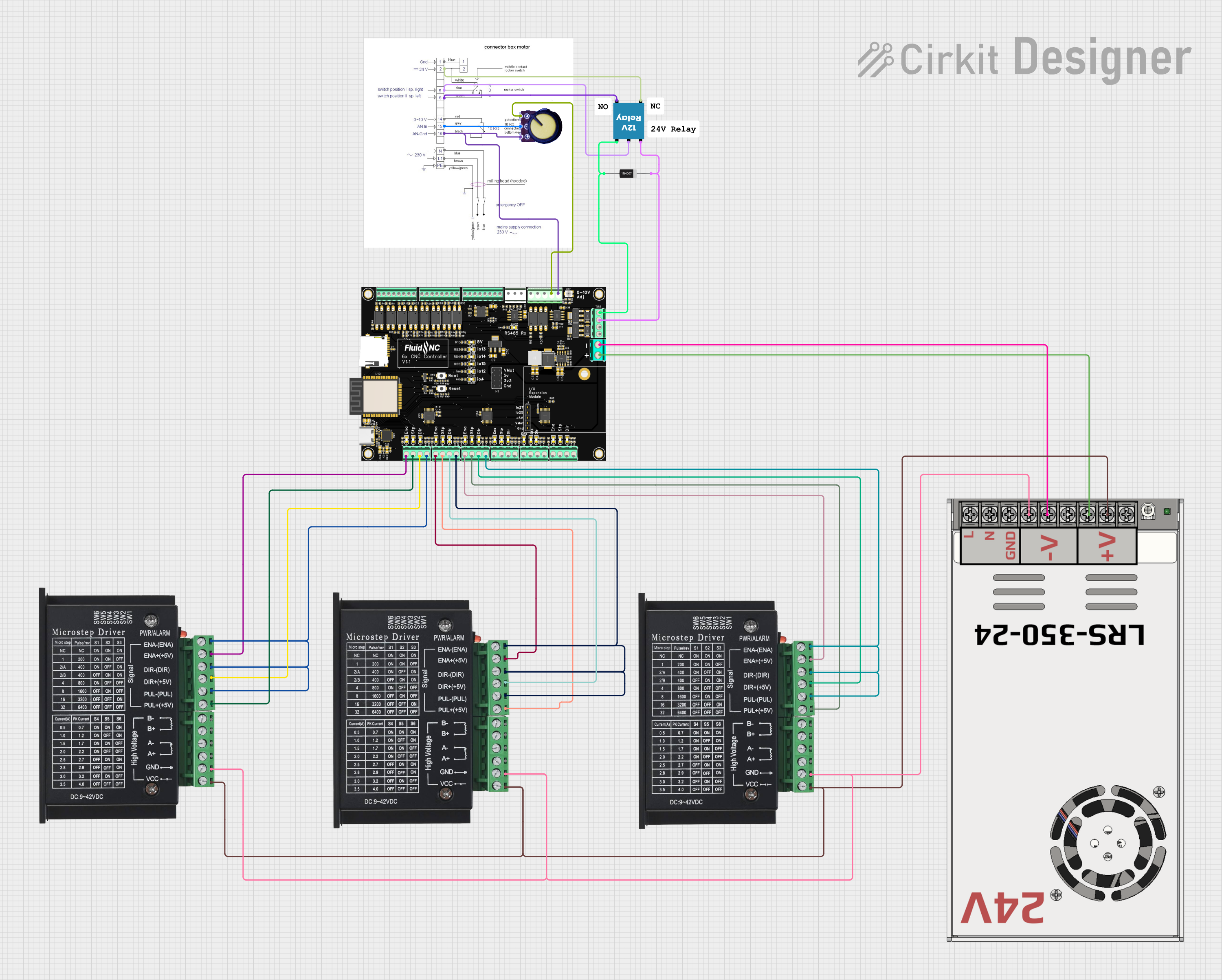

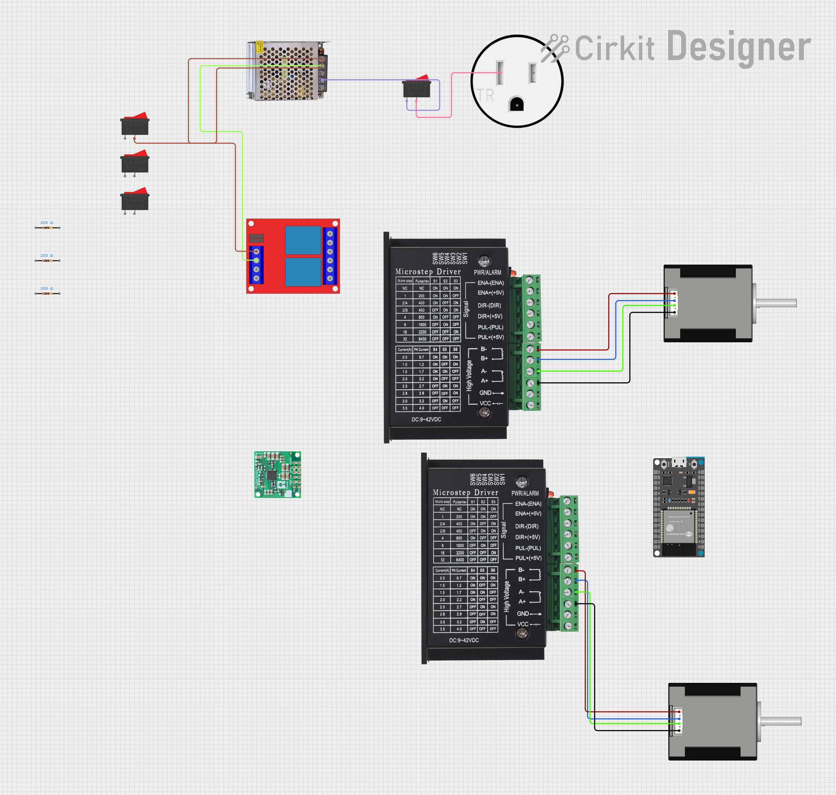
Explore Projects Built with Tb6600 4.5amps
Technical Specifications
Key Technical Details
| Parameter | Value |
|---|---|
| Manufacturer | Generic |
| Part ID | 10W |
| Input Voltage | 9V - 42V DC |
| Output Current | 0.2A - 4.5A |
| Microstepping | 1, 1/2, 1/4, 1/8, 1/16 |
| Control Signal | 3.3V - 24V |
| Operating Temperature | -10°C to +45°C |
| Dimensions | 96mm x 56mm x 33mm |
Pin Configuration and Descriptions
| Pin Name | Description |
|---|---|
| ENA+ | Enable Signal Positive |
| ENA- | Enable Signal Negative |
| DIR+ | Direction Signal Positive |
| DIR- | Direction Signal Negative |
| PUL+ | Pulse Signal Positive |
| PUL- | Pulse Signal Negative |
| A+ | Motor Coil A Positive |
| A- | Motor Coil A Negative |
| B+ | Motor Coil B Positive |
| B- | Motor Coil B Negative |
| VCC | Power Supply Positive (9V - 42V DC) |
| GND | Power Supply Negative |
Usage Instructions
How to Use the TB6600 in a Circuit
Power Supply Connection:
- Connect the VCC pin to a DC power supply (9V - 42V).
- Connect the GND pin to the ground of the power supply.
Motor Connection:
- Connect the A+ and A- pins to one coil of the stepper motor.
- Connect the B+ and B- pins to the other coil of the stepper motor.
Control Signal Connection:
- Connect the PUL+ and PUL- pins to the pulse signal source.
- Connect the DIR+ and DIR- pins to the direction signal source.
- Connect the ENA+ and ENA- pins to the enable signal source (optional).
Important Considerations and Best Practices
- Heat Dissipation: Ensure proper heat dissipation by mounting the TB6600 on a heat sink or using a cooling fan.
- Current Setting: Adjust the current setting using the DIP switches on the driver to match the stepper motor's rated current.
- Microstepping: Set the microstepping mode using the DIP switches to achieve the desired resolution.
- Signal Voltage: Ensure that the control signals are within the specified voltage range (3.3V - 24V).
Example: Connecting TB6600 to Arduino UNO
// Define pin connections
#define PUL_PIN 2  // Pulse pin
#define DIR_PIN 3  // Direction pin
#define ENA_PIN 4  // Enable pin

void setup() {
  pinMode(PUL_PIN, OUTPUT);
  pinMode(DIR_PIN, OUTPUT);
  pinMode(ENA_PIN, OUTPUT);

  digitalWrite(ENA_PIN, LOW);  // Enable the driver
}

void loop() {
  digitalWrite(DIR_PIN, HIGH);  // Set direction

  // Generate pulses to move the motor
  for (int i = 0; i < 200; i++) {
    digitalWrite(PUL_PIN, HIGH);
    delayMicroseconds(500);  // Adjust delay for speed control
    digitalWrite(PUL_PIN, LOW);
    delayMicroseconds(500);
  }

  delay(1000);  // Wait for a second

  digitalWrite(DIR_PIN, LOW);  // Change direction

  // Generate pulses to move the motor in the opposite direction
  for (int i = 0; i < 200; i++) {
    digitalWrite(PUL_PIN, HIGH);
    delayMicroseconds(500);
    digitalWrite(PUL_PIN, LOW);
    delayMicroseconds(500);
  }

  delay(1000);  // Wait for a second
}
Troubleshooting and FAQs
Common Issues
Motor Not Moving:
- Solution: Check the power supply connections and ensure the voltage is within the specified range. Verify that the control signals are correctly connected and within the voltage range.
Overheating:
- Solution: Ensure proper heat dissipation by using a heat sink or cooling fan. Check the current setting and adjust it to match the motor's rated current.
Erratic Motor Movement:
- Solution: Verify the microstepping settings and ensure they match the desired resolution. Check the control signal connections for any loose or incorrect wiring.
FAQs
Can I use the TB6600 with a 24V power supply?
- Yes, the TB6600 can handle input voltages from 9V to 42V DC.
How do I set the current limit on the TB6600?
- Use the DIP switches on the driver to set the current limit according to the stepper motor's rated current.
What is the maximum microstepping resolution of the TB6600?
- The TB6600 supports up to 1/16 microstepping.
Do I need to use the enable signal (ENA+ and ENA-)?
- The enable signal is optional. If not used, the driver will remain enabled by default.
By following this documentation, users can effectively utilize the TB6600 stepper motor driver in their projects, ensuring reliable and precise motor control.