How to Use CTVIB01 0-3.3V to 4-20mA Converter: Examples, Pinouts, and Specs
Introduction
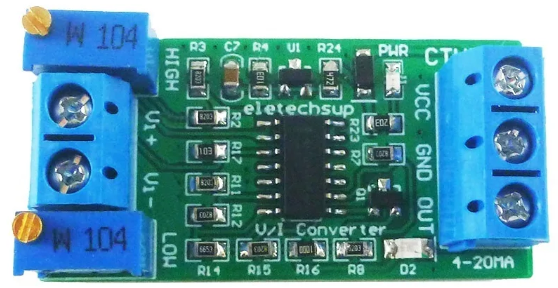
The CTVIB01 is a voltage-to-current converter manufactured by ELETECHSUP. It is designed to convert a voltage signal in the range of 0-3.3V into a standard industrial current signal of 4-20mA. This conversion is widely used in industrial automation, process control, and sensor data transmission, where current signals are preferred due to their resilience to noise and ability to travel long distances without significant signal degradation.
Explore Projects Built with CTVIB01 0-3.3V to 4-20mA Converter


Explore Projects Built with CTVIB01 0-3.3V to 4-20mA Converter
Common Applications
- Industrial Automation: Transmitting sensor data (e.g., temperature, pressure, or flow) to a central controller.
- Process Control Systems: Interfacing with Programmable Logic Controllers (PLCs) or Distributed Control Systems (DCS).
- Remote Monitoring: Sending analog signals over long distances in harsh environments.
- Analog Signal Conditioning: Converting low-voltage signals from microcontrollers or sensors into industry-standard current signals.
Technical Specifications
Key Specifications
| Parameter | Value |
|---|---|
| Input Voltage Range | 0-3.3V |
| Output Current Range | 4-20mA |
| Supply Voltage | 12-24V DC |
| Accuracy | ±0.1% of Full Scale |
| Operating Temperature | -40°C to +85°C |
| Dimensions | 50mm x 25mm x 15mm |
| Manufacturer Part ID | CTVIB01 |
Pin Configuration and Descriptions
The CTVIB01 has a simple 4-pin interface for easy integration into circuits. The pinout is as follows:
| Pin Number | Name | Description |
|---|---|---|
| 1 | V+ | Positive supply voltage (12-24V DC). |
| 2 | GND | Ground connection for the power supply and signal. |
| 3 | VIN | Input voltage signal (0-3.3V) to be converted to a 4-20mA current signal. |
| 4 | IOUT | Output current signal (4-20mA) proportional to the input voltage. |
Usage Instructions
How to Use the CTVIB01 in a Circuit
- Power Supply: Connect the V+ pin to a DC power supply (12-24V) and the GND pin to the ground of the power supply.
- Input Signal: Connect the voltage signal (0-3.3V) to the VIN pin. This signal can come from a microcontroller, sensor, or other voltage source.
- Output Signal: Connect the IOUT pin to the input of the receiving device (e.g., PLC, DCS, or analog input module). Ensure the receiving device is compatible with a 4-20mA current loop.
- Load Resistor: If required, place a load resistor (typically 250Ω) across the input terminals of the receiving device to convert the current signal back into a voltage signal for measurement.
Important Considerations
- Input Voltage Range: Ensure the input voltage does not exceed 3.3V, as this may damage the converter.
- Power Supply: Use a stable DC power supply within the specified range (12-24V) to ensure accurate operation.
- Wiring: Use shielded cables for long-distance connections to minimize noise interference.
- Calibration: If precise accuracy is required, calibrate the system by adjusting the input voltage and verifying the corresponding output current.
Example: Using CTVIB01 with Arduino UNO
The CTVIB01 can be used with an Arduino UNO to convert an analog output signal (0-3.3V) into a 4-20mA current signal. Below is an example setup and code:
Circuit Diagram
- Connect the V+ pin of the CTVIB01 to a 12V DC power supply.
- Connect the GND pin to the ground of the Arduino and the power supply.
- Connect the VIN pin to an analog output pin (e.g., PWM pin) of the Arduino.
- Connect the IOUT pin to the input of a 4-20mA receiver or load resistor.
Arduino Code
// Example code to generate a 0-3.3V signal using Arduino UNO
// This signal will be converted to a 4-20mA current by the CTVIB01

const int pwmPin = 9; // PWM pin connected to VIN of CTVIB01
const float maxVoltage = 3.3; // Maximum input voltage for CTVIB01
const int pwmResolution = 255; // 8-bit PWM resolution

void setup() {
  pinMode(pwmPin, OUTPUT); // Set the PWM pin as output
}

void loop() {
  // Generate a test signal: Sweep from 0 to 3.3V
  for (int i = 0; i <= pwmResolution; i++) {
    analogWrite(pwmPin, i); // Write PWM value to the pin
    delay(50); // Delay for 50ms to observe the change
  }
  delay(1000); // Pause for 1 second before repeating
}
Notes:
- Use a low-pass filter (e.g., RC filter) on the PWM output to smooth the signal if necessary.
- Ensure the Arduino's output voltage does not exceed 3.3V. If the Arduino operates at 5V, use a voltage divider or level shifter.
Troubleshooting and FAQs
Common Issues and Solutions
| Issue | Possible Cause | Solution |
|---|---|---|
| No output current from IOUT pin | Incorrect wiring or no power supply | Verify all connections and ensure the power supply is within 12-24V. |
| Output current is not 4-20mA | Input voltage out of range | Ensure the input voltage is within 0-3.3V. |
| Signal noise or instability | Long cables or unshielded wiring | Use shielded cables and minimize cable length where possible. |
| Overheating of the module | Excessive input voltage or current load | Check the input voltage and ensure the load is within specifications. |
FAQs
Can the CTVIB01 handle input voltages above 3.3V?
- No, the input voltage must not exceed 3.3V. Use a voltage divider or level shifter if your source voltage is higher.
What is the maximum distance for transmitting the 4-20mA signal?
- The maximum distance depends on the cable type and resistance, but typically, 4-20mA signals can travel up to 1,000 meters with proper wiring.
Can I use the CTVIB01 with a 5V microcontroller?
- Yes, but you must use a voltage divider or level shifter to ensure the input voltage to the CTVIB01 does not exceed 3.3V.
Is the CTVIB01 suitable for outdoor use?
- The module itself is not weatherproof. Use an appropriate enclosure for outdoor applications.
By following this documentation, users can effectively integrate the CTVIB01 into their projects and ensure reliable operation in industrial and automation systems.