How to Use ESP32 Expansion Board for ESP32/ESP32-S3 Core Modules: Examples, Pinouts, and Specs
Introduction
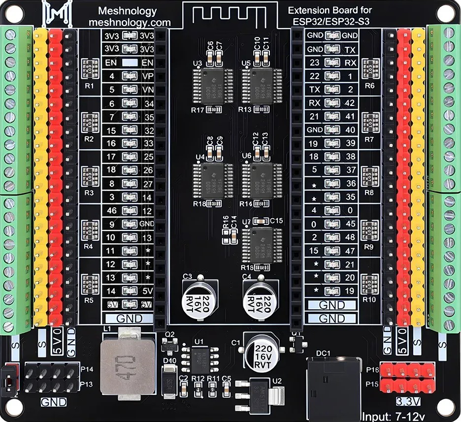
The ESP32 Expansion Board (Meshnology N40) is a versatile accessory designed to enhance the functionality of ESP32 and ESP32-S3 core modules. This expansion board simplifies prototyping and development by providing additional GPIO pins, power management features, and connectivity options. It is ideal for IoT projects, robotics, home automation, and other applications requiring reliable and scalable hardware integration.
Explore Projects Built with ESP32 Expansion Board for ESP32/ESP32-S3 Core Modules
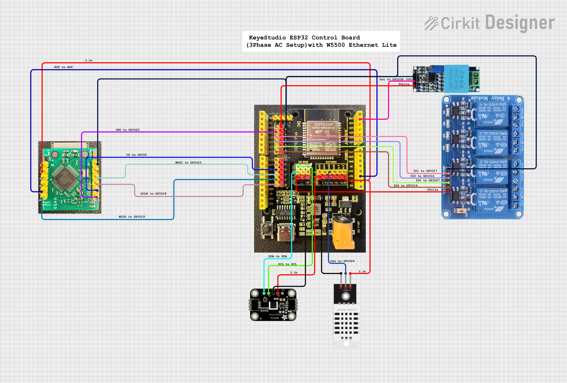


Explore Projects Built with ESP32 Expansion Board for ESP32/ESP32-S3 Core Modules
Common Applications and Use Cases
- IoT devices and smart home systems
- Robotics and automation projects
- Prototyping and testing ESP32/ESP32-S3-based designs
- Educational and research purposes
- Projects requiring multiple GPIOs or external peripherals
Technical Specifications
Key Technical Details
| Parameter | Specification |
|---|---|
| Manufacturer | Meshnology |
| Part ID | N40 |
| Compatible Modules | ESP32, ESP32-S3 Core Modules |
| Input Voltage Range | 5V (via USB-C) or 7-12V (via DC barrel jack) |
| GPIO Pin Count | Up to 38 (depending on the ESP32 module used) |
| Communication Interfaces | UART, SPI, I2C, PWM |
| Power Management | Onboard 3.3V voltage regulator, 5V passthrough |
| USB Interface | USB-C for programming and power |
| Dimensions | 60mm x 40mm x 15mm |
| Operating Temperature | -40°C to 85°C |
Pin Configuration and Descriptions
The ESP32 Expansion Board provides easy access to the GPIO pins of the ESP32/ESP32-S3 module. Below is the pinout description:
| Pin Name | Description |
|---|---|
| 3V3 | 3.3V output from the onboard regulator |
| GND | Ground |
| VIN | Input voltage (7-12V via DC barrel jack) |
| GPIO0-GPIO39 | General-purpose input/output pins |
| TXD | UART Transmit |
| RXD | UART Receive |
| SCL | I2C Clock |
| SDA | I2C Data |
| MOSI | SPI Master Out Slave In |
| MISO | SPI Master In Slave Out |
| SCK | SPI Clock |
| EN | Enable pin for the ESP32 module |
| BOOT | Boot mode selection pin |
Usage Instructions
How to Use the Component in a Circuit
Powering the Board:
- Connect a USB-C cable to the board for power and programming.
- Alternatively, use a 7-12V DC power supply via the barrel jack.
Connecting the ESP32/ESP32-S3 Module:
- Insert the ESP32 or ESP32-S3 core module into the designated socket on the expansion board.
- Ensure proper alignment of the pins to avoid damage.
Accessing GPIO Pins:
- Use the labeled headers to connect external components (e.g., sensors, actuators).
- Refer to the pinout table for the correct pin assignments.
Programming the ESP32:
- Connect the board to your computer via USB-C.
- Use the Arduino IDE or ESP-IDF to upload code to the ESP32 module.
Using Communication Interfaces:
- Connect peripherals (e.g., I2C sensors, SPI displays) to the corresponding pins.
- Configure the communication protocols in your code.
Important Considerations and Best Practices
- Ensure the input voltage does not exceed the specified range to prevent damage.
- Avoid shorting GPIO pins or connecting them to voltages higher than 3.3V.
- Use proper decoupling capacitors when connecting external components to reduce noise.
- When using the board in high-current applications, ensure adequate heat dissipation.
Example Code for Arduino UNO Integration
Below is an example of using the ESP32 Expansion Board with an I2C sensor:
#include <Wire.h>

// Define I2C pins for ESP32
#define SDA_PIN 21  // SDA pin on the expansion board
#define SCL_PIN 22  // SCL pin on the expansion board

void setup() {
  // Initialize serial communication for debugging
  Serial.begin(115200);

  // Initialize I2C communication
  Wire.begin(SDA_PIN, SCL_PIN);
  Serial.println("I2C initialized successfully.");
}

void loop() {
  // Example: Scan for I2C devices
  Serial.println("Scanning for I2C devices...");
  byte error, address;
  int nDevices = 0;

  for (address = 1; address < 127; address++) {
    Wire.beginTransmission(address);
    error = Wire.endTransmission();

    if (error == 0) {
      Serial.print("I2C device found at address 0x");
      if (address < 16) Serial.print("0");
      Serial.println(address, HEX);
      nDevices++;
    }
  }

  if (nDevices == 0) {
    Serial.println("No I2C devices found.");
  } else {
    Serial.println("I2C scan complete.");
  }

  delay(5000);  // Wait 5 seconds before scanning again
}
Troubleshooting and FAQs
Common Issues Users Might Face
ESP32 Module Not Detected:
- Ensure the module is properly seated in the socket.
- Verify the USB-C cable is functional and supports data transfer.
Power Issues:
- Check the input voltage and ensure it is within the specified range.
- Verify the onboard voltage regulator is functioning correctly.
GPIO Pins Not Responding:
- Confirm the correct pin numbers are used in the code.
- Check for loose or incorrect connections to external components.
I2C/SPI Communication Fails:
- Verify the wiring of the connected peripherals.
- Ensure the correct pins are defined in the code.
Solutions and Tips for Troubleshooting
- Use a multimeter to check voltage levels at the power and GPIO pins.
- Test the ESP32 module separately to rule out hardware issues.
- Update the ESP32 firmware and libraries to the latest versions.
- Refer to the ESP32 datasheet for detailed information on pin functions and limitations.
By following this documentation, users can effectively utilize the Meshnology N40 ESP32 Expansion Board to enhance their projects and streamline development workflows.