Cirkit Designer Logo
Cirkit Designer
Your all-in-one circuit design IDE
Home / 
Component Documentation

How to Use Adafruit NeoKey 1x4 QT I2C: Examples, Pinouts, and Specs

Image of Adafruit NeoKey 1x4 QT I2C
Cirkit Designer LogoDesign with Adafruit NeoKey 1x4 QT I2C in Cirkit Designer

Introduction

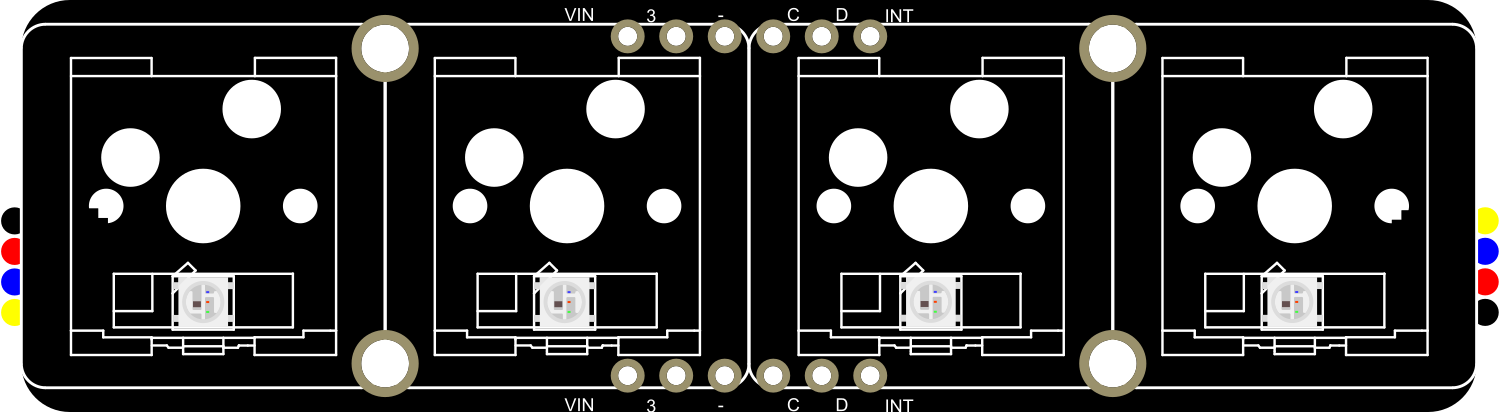
The Adafruit NeoKey 1x4 QT is a versatile and compact key switch module that features four individual keys. Each key is equipped with a NeoPixel RGB LED, allowing for customizable color feedback. The module communicates over I2C, making it simple to integrate into projects with limited GPIO availability. It also includes STEMMA QT connectors for quick and solderless connections. This component is ideal for creating custom keyboards, input devices, or interactive projects that require user input with visual feedback.

Common applications include:

  • DIY keyboards
  • Interactive art installations
  • Custom control panels for electronics projects
  • Educational tools for learning about I2C communication

Explore Projects Built with Adafruit NeoKey 1x4 QT I2C

Use Cirkit Designer to design, explore, and prototype these projects online. Some projects support real-time simulation. Click "Open Project" to start designing instantly!
Arduino UNO 4x4 Keypad Input Display on 16x2 I2C LCD
Image of Arduino Uno - Keypad/LCD (Sim-C): A project utilizing Adafruit NeoKey 1x4 QT I2C in a practical application
This circuit interfaces a 4x4 keypad with an Arduino UNO to capture user input, which is then displayed on a 16x2 I2C LCD. The keypad is connected to the digital pins D2 to D9 of the Arduino, while the LCD is connected via the I2C interface (SDA and SCL pins).
Cirkit Designer LogoOpen Project in Cirkit Designer
Arduino Nano-Based Dual 4x4 Keypad Interface with LCD Display and NRF24L01 Wireless Communication
Image of Sumit-radio-Reciver: A project utilizing Adafruit NeoKey 1x4 QT I2C in a practical application
This circuit features an Arduino Nano microcontroller interfaced with two 4x4 membrane matrix keypads, an NRF24L01 wireless module, and a 20x4 I2C LCD display. The keypads are connected through resistors to the Arduino for input detection, while the NRF24L01 module enables wireless communication, and the LCD display provides visual output. The setup and loop functions in the Arduino code are placeholders for further development.
Cirkit Designer LogoOpen Project in Cirkit Designer
Arduino Mega 2560-Based Smart Home Control System with LCD Display and Flame Sensor
Image of Copy of schoolproject (1): A project utilizing Adafruit NeoKey 1x4 QT I2C in a practical application
This circuit is a multi-functional embedded system featuring an Arduino Mega 2560 microcontroller that interfaces with a 4x4 membrane keypad, a 20x4 I2C LCD, an 8x8 LED matrix, a DS3231 RTC module, a passive buzzer, and a KY-026 flame sensor. The system is powered by a 5V PSU and is designed to provide real-time clock functionality, user input via the keypad, visual output on the LCD and LED matrix, and flame detection with an audible alert.
Cirkit Designer LogoOpen Project in Cirkit Designer
Arduino UNO R4 WiFi Controlled Access System with I2C LCD and Keypad
Image of arduino r4 wifi: A project utilizing Adafruit NeoKey 1x4 QT I2C in a practical application
This circuit features an Arduino UNO R4 WiFi connected to an I2C LCD 16x2 Screen and a 4x4 Membrane Matrix Keypad. The Arduino controls the LCD to prompt for and display a password input from the keypad, granting or denying access based on the correctness of the entered password. The keypad's rows and columns are interfaced with the Arduino's digital pins, while the LCD uses I2C communication via the Arduino's analog pins configured for SDA and SCL.
Cirkit Designer LogoOpen Project in Cirkit Designer

Explore Projects Built with Adafruit NeoKey 1x4 QT I2C

Use Cirkit Designer to design, explore, and prototype these projects online. Some projects support real-time simulation. Click "Open Project" to start designing instantly!
Image of Arduino Uno - Keypad/LCD (Sim-C): A project utilizing Adafruit NeoKey 1x4 QT I2C in a practical application
Arduino UNO 4x4 Keypad Input Display on 16x2 I2C LCD
This circuit interfaces a 4x4 keypad with an Arduino UNO to capture user input, which is then displayed on a 16x2 I2C LCD. The keypad is connected to the digital pins D2 to D9 of the Arduino, while the LCD is connected via the I2C interface (SDA and SCL pins).
Cirkit Designer LogoOpen Project in Cirkit Designer
Image of Sumit-radio-Reciver: A project utilizing Adafruit NeoKey 1x4 QT I2C in a practical application
Arduino Nano-Based Dual 4x4 Keypad Interface with LCD Display and NRF24L01 Wireless Communication
This circuit features an Arduino Nano microcontroller interfaced with two 4x4 membrane matrix keypads, an NRF24L01 wireless module, and a 20x4 I2C LCD display. The keypads are connected through resistors to the Arduino for input detection, while the NRF24L01 module enables wireless communication, and the LCD display provides visual output. The setup and loop functions in the Arduino code are placeholders for further development.
Cirkit Designer LogoOpen Project in Cirkit Designer
Image of Copy of schoolproject (1): A project utilizing Adafruit NeoKey 1x4 QT I2C in a practical application
Arduino Mega 2560-Based Smart Home Control System with LCD Display and Flame Sensor
This circuit is a multi-functional embedded system featuring an Arduino Mega 2560 microcontroller that interfaces with a 4x4 membrane keypad, a 20x4 I2C LCD, an 8x8 LED matrix, a DS3231 RTC module, a passive buzzer, and a KY-026 flame sensor. The system is powered by a 5V PSU and is designed to provide real-time clock functionality, user input via the keypad, visual output on the LCD and LED matrix, and flame detection with an audible alert.
Cirkit Designer LogoOpen Project in Cirkit Designer
Image of arduino r4 wifi: A project utilizing Adafruit NeoKey 1x4 QT I2C in a practical application
Arduino UNO R4 WiFi Controlled Access System with I2C LCD and Keypad
This circuit features an Arduino UNO R4 WiFi connected to an I2C LCD 16x2 Screen and a 4x4 Membrane Matrix Keypad. The Arduino controls the LCD to prompt for and display a password input from the keypad, granting or denying access based on the correctness of the entered password. The keypad's rows and columns are interfaced with the Arduino's digital pins, while the LCD uses I2C communication via the Arduino's analog pins configured for SDA and SCL.
Cirkit Designer LogoOpen Project in Cirkit Designer

Technical Specifications

Key Technical Details

  • Operating Voltage: 3.3V to 5V
  • I2C Addresses: 0x30 to 0x3F (adjustable with solder jumpers)
  • Backlight: Individually addressable RGB NeoPixel LEDs
  • Key Switch Type: Mechanical (Cherry MX compatible)
  • Communication: I2C (Two-wire serial interface)
  • Connectors: STEMMA QT / Qwiic

Pin Configuration and Descriptions

Pin Number Name Description
1 VCC Power supply (3.3V to 5V)
2 GND Ground connection
3 SDA I2C Data Line
4 SCL I2C Clock Line
5-8 K1-K4 Key inputs (not directly accessible, used internally)

Usage Instructions

Integrating with a Circuit

  1. Powering the Module: Connect the VCC pin to a 3.3V or 5V power supply, and the GND pin to the ground.
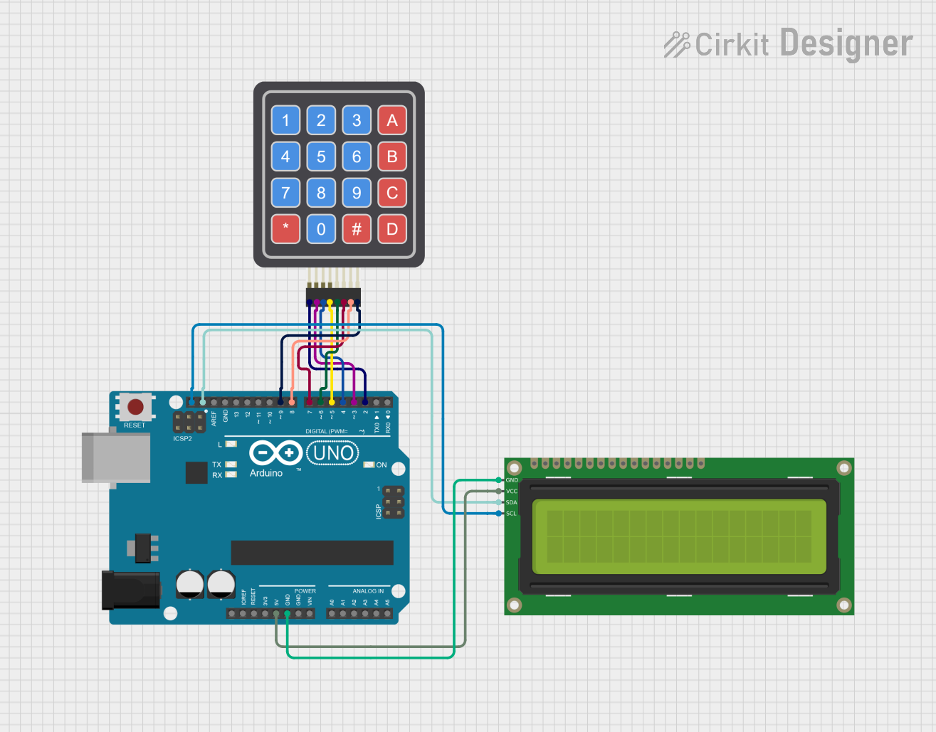
  2. I2C Communication: Connect the SDA and SCL pins to the corresponding SDA and SCL pins on your microcontroller (e.g., Arduino UNO).
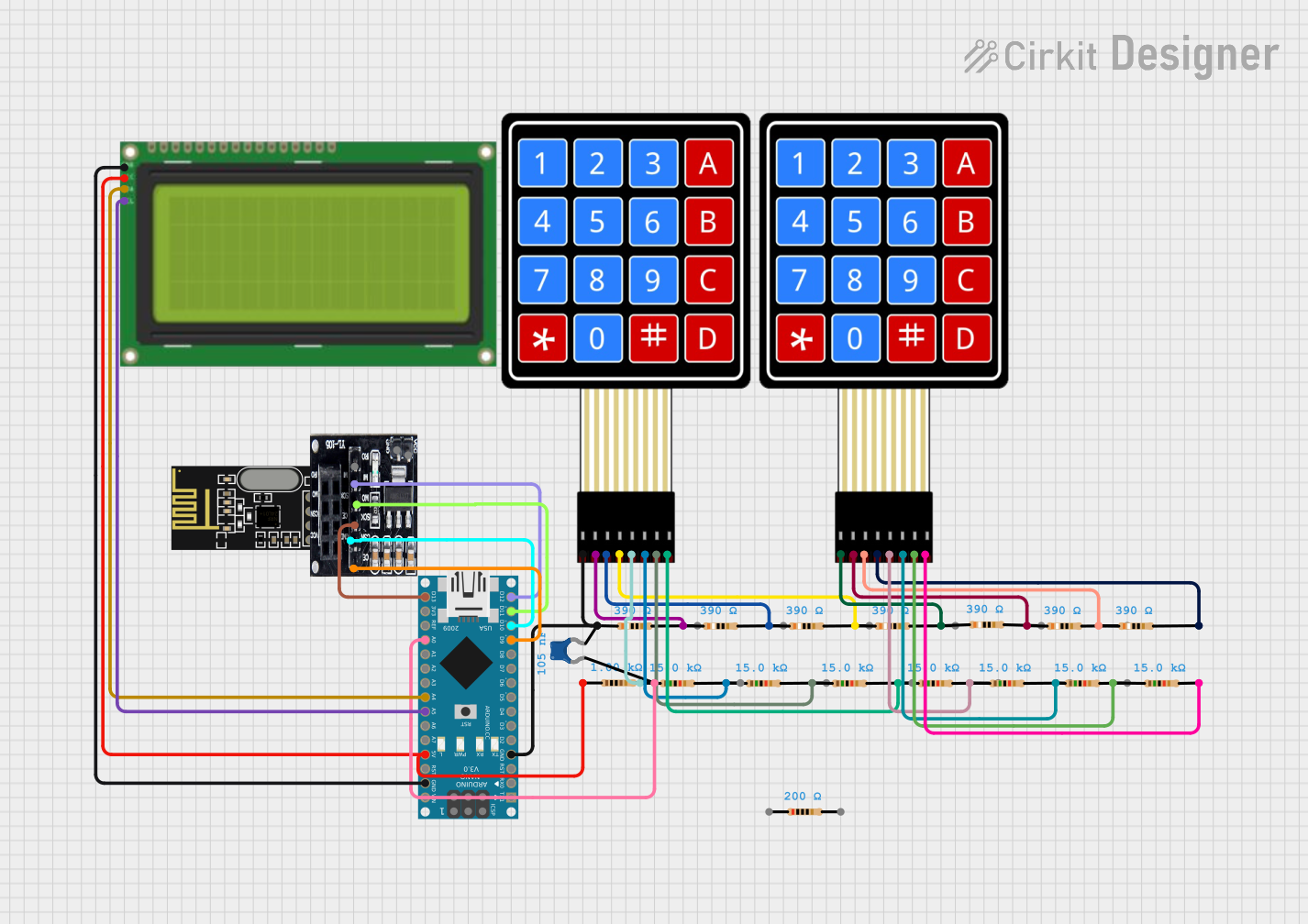
  3. Address Configuration: If using multiple NeoKey modules, set unique I2C addresses using the solder jumpers on the back of the PCB.

Best Practices

  • Use pull-up resistors on the I2C lines if they are not already present on the microcontroller board.
  • Avoid long I2C cable runs to minimize signal degradation.
  • Ensure that the power supply can handle the current draw of the LEDs, especially if multiple modules are chained together.

Example Code for Arduino UNO

#include <Wire.h>
#include <Adafruit_NeoPixel.h>
#include <Adafruit_NeoKey_1x4.h>

// Define the I2C address for the NeoKey 1x4
#define NEOKEY_I2C_ADDRESS 0x30

// Create the NeoKey object
Adafruit_NeoKey_1x4 neokey = Adafruit_NeoKey_1x4();

void setup() {
  // Initialize serial communication for debugging
  Serial.begin(9600);

  // Initialize the NeoKey 1x4
  if (!neokey.begin(NEOKEY_I2C_ADDRESS)) {
    Serial.println("Failed to find NeoKey, check wiring!");
    while (1) delay(10);
  }
}

void loop() {
  // Read the key states
  uint8_t keyState = neokey.read();

  // Check each key and set the color accordingly
  for (int i = 0; i < 4; i++) {
    if (keyState & (1 << i)) {
      // If key is pressed, set to red
      neokey.setPixelColor(i, 255, 0, 0);
    } else {
      // If key is not pressed, set to green
      neokey.setPixelColor(i, 0, 255, 0);
    }
  }

  // Update the NeoPixels
  neokey.show();

  // Small delay to debounce
  delay(10);
}

Troubleshooting and FAQs

Common Issues

  • LEDs not lighting up: Ensure the module is correctly powered and the I2C communication is properly established.
  • No response from keys: Check the I2C connections and ensure the correct I2C address is used in the code.
  • Multiple modules not working together: Verify that each module has a unique I2C address and the connections are secure.

Solutions and Tips

  • Power Issues: Use an external power supply if the current draw of the LEDs is too high for the microcontroller's regulator.
  • I2C Communication: Use the Wire library's Wire.setClock() function to lower the I2C clock speed if experiencing communication issues.
  • Addressing Modules: Consult the NeoKey 1x4 datasheet for instructions on setting the I2C address using the solder jumpers.

FAQs

Q: Can I use the NeoKey 1x4 with a 3.3V microcontroller? A: Yes, the NeoKey 1x4 is compatible with both 3.3V and 5V logic levels.

Q: How do I chain multiple NeoKey 1x4 modules together? A: Connect the STEMMA QT connectors from one module to the next, ensuring that each module has a unique I2C address.

Q: What type of key switches can I use with the NeoKey 1x4? A: The NeoKey 1x4 is designed to be compatible with Cherry MX style mechanical key switches.

Q: How do I change the color of the NeoPixels? A: Use the neokey.setPixelColor(index, red, green, blue) function, where index is the key number (0-3) and red, green, blue are the color values (0-255).