
How to Use ADS1115: Examples, Pinouts, and Specs
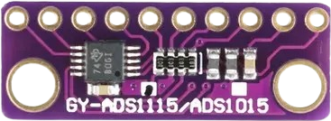
 Design with ADS1115 in Cirkit Designer
Introduction
The ADS1115 is a high-precision 16-bit analog-to-digital converter (ADC) with an integrated programmable gain amplifier (PGA). It is designed to measure small analog signals with high accuracy and convert them into digital values for processing by microcontrollers or other digital systems. The ADS1115 supports four single-ended or two differential input channels, making it versatile for a wide range of applications. It communicates via an I2C interface, simplifying integration with microcontrollers, such as Arduino or Raspberry Pi. Additionally, it includes a built-in comparator for threshold-based signal monitoring.
Explore Projects Built with ADS1115
 Open Project in Cirkit Designer
 Open Project in Cirkit Designer
 Open Project in Cirkit Designer
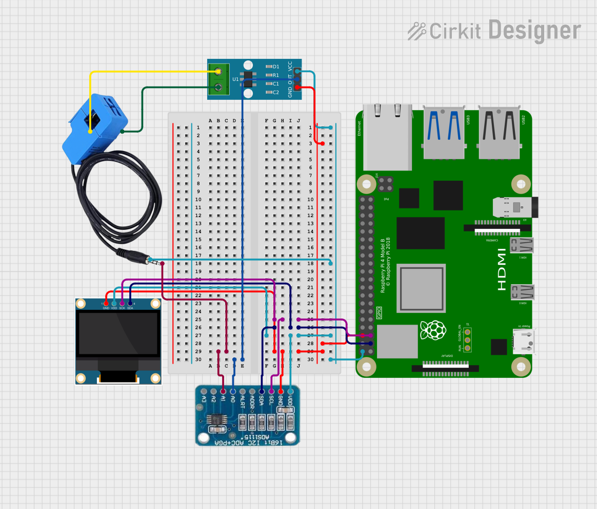 Open Project in Cirkit Designer
Explore Projects Built with ADS1115
Open Project in Cirkit DesignerOpen Project in Cirkit DesignerOpen Project in Cirkit DesignerOpen Project in Cirkit DesignerCommon Applications
- Sensor data acquisition (e.g., temperature, pressure, or light sensors)
- Battery monitoring and management systems
- Industrial process control
- Portable instrumentation
- Data logging systems
Technical Specifications
Key Technical Details
| Parameter | Value |
|---|---|
| Resolution | 16-bit |
| Input Channels | 4 single-ended or 2 differential |
| Input Voltage Range | 0 to VDD (single-ended) |
| Programmable Gain Options | ±0.256V to ±6.144V |
| Supply Voltage (VDD) | 2.0V to 5.5V |
| Interface | I2C (up to 3.4 MHz) |
| Data Rate | Programmable: 8 SPS to 860 SPS |
| Operating Temperature | -40°C to +125°C |
| Comparator Functionality | Built-in, configurable |
Pin Configuration
The ADS1115 is typically available in an 8-pin package. Below is the pinout and description:
| Pin Number | Pin Name | Description |
|---|---|---|
| 1 | VDD | Power supply input (2.0V to 5.5V) |
| 2 | GND | Ground |
| 3 | SCL | I2C clock line |
| 4 | SDA | I2C data line |
| 5 | ALERT/RDY | Comparator output or data ready signal |
| 6 | A0 | I2C address selection bit 0 |
| 7 | A1 | I2C address selection bit 1 |
| 8 | ADDR | I2C address configuration (GND/VDD/SCL/SDA) |
Usage Instructions
Using the ADS1115 in a Circuit
- Power Supply: Connect the VDD pin to a 2.0V–5.5V power source and the GND pin to ground.
- I2C Communication: Connect the SCL and SDA pins to the corresponding I2C pins on your microcontroller. Use pull-up resistors (typically 4.7kΩ) on both lines.
- Input Signal: Connect your analog signal to one of the input channels (A0–A3 for single-ended or A0/A1, A2/A3 for differential).
- Address Configuration: Set the I2C address by connecting the ADDR pin to GND, VDD, SCL, or SDA. This allows up to four ADS1115 devices on the same I2C bus.
- Comparator (Optional): Use the ALERT/RDY pin for threshold-based monitoring or as a data-ready signal.
Important Considerations
- Input Voltage Range: Ensure the input signal does not exceed the PGA range or the supply voltage (VDD).
- I2C Pull-Up Resistors: Proper pull-up resistors are required for reliable I2C communication.
- Bypass Capacitor: Place a 0.1µF ceramic capacitor close to the VDD pin for power supply decoupling.
- Data Rate: Choose an appropriate data rate for your application to balance speed and noise performance.
Example Code for Arduino UNO
Below is an example of how to use the ADS1115 with an Arduino UNO to read a single-ended input:
#include <Wire.h>
#include <Adafruit_ADS1X15.h>

// Create an ADS1115 object
Adafruit_ADS1115 ads;

void setup() {
  Serial.begin(9600); // Initialize serial communication
  while (!Serial);    // Wait for Serial Monitor to open

  // Initialize the ADS1115
  if (!ads.begin()) {
    Serial.println("Failed to initialize ADS1115!");
    while (1); // Halt execution if initialization fails
  }
  Serial.println("ADS1115 initialized.");
}

void loop() {
  // Read a single-ended input (A0)
  int16_t adcValue = ads.readADC_SingleEnded(0);

  // Convert the ADC value to voltage
  float voltage = adcValue * 0.1875 / 1000; // 0.1875mV per bit for default gain

  // Print the results
  Serial.print("ADC Value: ");
  Serial.print(adcValue);
  Serial.print(" | Voltage: ");
  Serial.print(voltage, 4); // Print voltage with 4 decimal places
  Serial.println(" V");

  delay(1000); // Wait 1 second before the next reading
}
Notes on the Code
- The
Adafruit_ADS1X15library is used for simplified communication with the ADS1115. - The default PGA setting is ±6.144V, resulting in a resolution of 0.1875mV per bit.
- Modify the
readADC_SingleEnded()function to read from other channels (e.g.,readADC_SingleEnded(1)for A1).
Troubleshooting and FAQs
Common Issues
No I2C Communication:
- Ensure the SCL and SDA lines are connected correctly.
- Verify that pull-up resistors are present on the I2C lines.
- Check the I2C address configuration (ADDR pin).
Incorrect Readings:
- Confirm that the input signal is within the PGA range and supply voltage.
- Verify the gain setting in your code matches the expected input range.
ADS1115 Not Detected:
- Ensure the device is powered correctly (VDD and GND).
- Use an I2C scanner sketch to detect the ADS1115 on the bus.
FAQs
Q: Can I use the ADS1115 with a 3.3V microcontroller?
A: Yes, the ADS1115 operates with a supply voltage of 2.0V–5.5V and is compatible with 3.3V logic levels.
Q: How do I measure differential signals?
A: Connect the positive signal to one channel (e.g., A0) and the negative signal to another (e.g., A1). Use the readADC_Differential_0_1() function in the Adafruit library.
Q: What is the maximum sampling rate?
A: The ADS1115 supports a maximum data rate of 860 samples per second (SPS).
Q: Can I connect multiple ADS1115 devices to the same I2C bus?
A: Yes, up to four devices can be connected by configuring the ADDR pin to different states (GND, VDD, SCL, SDA).