How to Use ESP32-S3-DevKitC-1: Examples, Pinouts, and Specs
Introduction
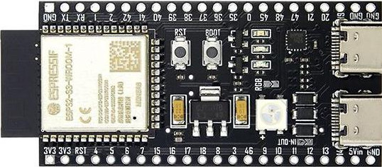
The ESP32-S3-DevKitC-1 is a development board manufactured by GENERIC, featuring the ESP32-S3 chip. This board is designed for IoT applications and prototyping, offering integrated Wi-Fi and Bluetooth connectivity. It supports a wide range of peripherals, making it ideal for developers working on smart devices, home automation, wearables, and other connected projects.
The ESP32-S3 chip includes a dual-core Xtensa LX7 processor, AI acceleration, and enhanced security features, making it suitable for both simple and complex IoT solutions. The board is compact, easy to use, and compatible with popular development environments like Arduino IDE and ESP-IDF.
Explore Projects Built with ESP32-S3-DevKitC-1


Explore Projects Built with ESP32-S3-DevKitC-1
Common Applications
- IoT devices and smart home systems
- Wearable electronics
- Industrial automation
- AI and machine learning applications
- Wireless sensor networks
- Prototyping and educational projects
Technical Specifications
Key Technical Details
| Parameter | Value |
|---|---|
| Manufacturer | GENERIC |
| Part ID | YD-ESP32-23 2022-V1.3 |
| Microcontroller | ESP32-S3 (Xtensa® 32-bit LX7 dual-core processor) |
| Wireless Connectivity | Wi-Fi 802.11 b/g/n, Bluetooth 5.0 LE |
| Flash Memory | 8 MB (default, may vary by model) |
| PSRAM | 8 MB (default, may vary by model) |
| Operating Voltage | 3.3V |
| Input Voltage Range | 5V (via USB) |
| GPIO Pins | 21 (configurable for digital, analog, I2C, SPI, UART, PWM, etc.) |
| USB Interface | USB Type-C (supports programming and power supply) |
| Dimensions | 54 mm x 25.5 mm |
| Operating Temperature | -40°C to +85°C |
Pin Configuration and Descriptions
| Pin Name | Pin Number | Description |
|---|---|---|
| 3V3 | 1 | 3.3V power output |
| GND | 2, 15 | Ground connection |
| EN | 3 | Enable pin (active high, resets the chip when pulled low) |
| IO0 | 4 | GPIO0, used for boot mode selection during programming |
| IO1 | 5 | GPIO1, general-purpose I/O |
| IO2 | 6 | GPIO2, general-purpose I/O |
| IO3 | 7 | GPIO3, general-purpose I/O |
| IO4 | 8 | GPIO4, general-purpose I/O |
| IO5 | 9 | GPIO5, general-purpose I/O |
| IO6-IO21 | 10-25 | Additional GPIO pins (configurable for various functions) |
| TXD0 | 26 | UART0 transmit pin |
| RXD0 | 27 | UART0 receive pin |
| USB_DM | 28 | USB D- (data line for USB communication) |
| USB_DP | 29 | USB D+ (data line for USB communication) |
Usage Instructions
How to Use the ESP32-S3-DevKitC-1 in a Circuit
Powering the Board:
- Connect the board to a computer or USB power source using a USB Type-C cable.
- Ensure the input voltage is 5V via USB. The onboard voltage regulator will provide 3.3V to the ESP32-S3 chip.
Programming the Board:
- Install the required drivers for the USB-to-serial interface (if not already installed).
- Use a development environment like Arduino IDE or ESP-IDF.
- Select the correct board (e.g., "ESP32-S3 Dev Module") and port in the IDE.
- Write your code and upload it to the board.
Connecting Peripherals:
- Use the GPIO pins to connect sensors, actuators, or other peripherals.
- Configure the pins in your code for the desired functionality (e.g., digital input/output, I2C, SPI).
Boot Mode Selection:
- To enter bootloader mode for programming, hold the IO0 button while pressing the EN button.
- Release the EN button first, then release the IO0 button.
Important Considerations and Best Practices
- Voltage Levels: Ensure all connected peripherals operate at 3.3V logic levels to avoid damaging the board.
- Pin Multiplexing: Many GPIO pins have multiple functions (e.g., UART, I2C, SPI). Check the ESP32-S3 datasheet to avoid conflicts.
- Power Supply: If using external power, ensure it is regulated to 3.3V.
- Heat Management: The board may heat up during operation, especially when using Wi-Fi or Bluetooth. Ensure proper ventilation.
Example Code for Arduino IDE
The following example demonstrates how to blink an LED connected to GPIO2:
// Define the GPIO pin for the LED
#define LED_PIN 2

void setup() {
  // Set the LED pin as an output
  pinMode(LED_PIN, OUTPUT);
}

void loop() {
  // Turn the LED on
  digitalWrite(LED_PIN, HIGH);
  delay(1000); // Wait for 1 second

  // Turn the LED off
  digitalWrite(LED_PIN, LOW);
  delay(1000); // Wait for 1 second
}
Troubleshooting and FAQs
Common Issues and Solutions
The board is not detected by the computer:
- Ensure the USB cable is functional and supports data transfer.
- Install the correct USB-to-serial drivers for the ESP32-S3.
- Check if the board is in bootloader mode (hold IO0 and press EN).
Code upload fails:
- Verify the correct board and port are selected in the IDE.
- Ensure no other application is using the COM port.
- Check the USB connection and try entering bootloader mode manually.
Wi-Fi or Bluetooth is not working:
- Ensure the correct credentials or pairing settings are used in your code.
- Check for interference from other devices or networks.
- Verify the antenna is not obstructed.
GPIO pins are not functioning as expected:
- Confirm the pin configuration in your code matches the intended use.
- Check for pin conflicts due to multiplexing.
- Ensure the connected peripherals are operating at 3.3V logic levels.
FAQs
Q: Can I power the board using an external 3.3V source?
A: Yes, you can power the board via the 3V3 pin, but ensure the voltage is stable and regulated.
Q: Is the ESP32-S3-DevKitC-1 compatible with Arduino libraries?
A: Yes, the board is compatible with most Arduino libraries, but some may require modifications for the ESP32-S3 architecture.
Q: How do I reset the board?
A: Press the EN button to reset the board.
Q: Can I use the board for AI applications?
A: Yes, the ESP32-S3 includes AI acceleration features, making it suitable for lightweight AI and ML tasks.