How to Use GMT020 display2: Examples, Pinouts, and Specs
Introduction
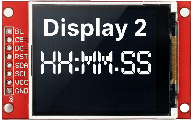
The GMT020 Display2 is a compact digital display module designed for presenting numerical data in a clear and efficient manner. It typically features a 7-segment or LCD format, making it ideal for applications requiring precise and easily readable output. This module is widely used in devices such as digital clocks, voltmeters, temperature monitors, and other measurement or control systems.
Explore Projects Built with GMT020 display2


Explore Projects Built with GMT020 display2
Common Applications and Use Cases
- Digital clocks and timers
- Voltage and current measurement displays
- Temperature and humidity monitors
- Consumer electronics with numerical output
- Industrial control panels
Technical Specifications
The GMT020 Display2 is designed to operate efficiently in a variety of electronic systems. Below are its key technical details:
General Specifications
| Parameter | Value |
|---|---|
| Display Type | 7-segment or LCD |
| Number of Digits | 2 |
| Operating Voltage | 3.3V to 5V |
| Operating Current | 20mA (typical) |
| Viewing Angle | 120° |
| Operating Temperature | -20°C to 70°C |
| Dimensions | 25mm x 15mm x 5mm |
Pin Configuration and Descriptions
The GMT020 Display2 module typically has a 10-pin interface. Below is the pinout and description:
| Pin Number | Name | Description |
|---|---|---|
| 1 | VCC | Power supply input (3.3V to 5V) |
| 2 | GND | Ground connection |
| 3 | D1 | Segment control for digit 1 |
| 4 | D2 | Segment control for digit 2 |
| 5 | A | Segment A control |
| 6 | B | Segment B control |
| 7 | C | Segment C control |
| 8 | D | Segment D control |
| 9 | E | Segment E control |
| 10 | F | Segment F control |
Usage Instructions
The GMT020 Display2 is straightforward to integrate into a circuit. Below are the steps and considerations for using this module effectively:
Connecting the Display
- Power Supply: Connect the
VCCpin to a 3.3V or 5V power source and theGNDpin to the ground of your circuit. - Segment Control: Use the segment pins (
A,B,C,D,E,F) to control the individual segments of the display. These pins are typically connected to a microcontroller or driver IC. - Digit Selection: Use the
D1andD2pins to select which digit is active. This is often done using multiplexing.
Important Considerations
- Current Limiting: Use appropriate resistors (e.g., 220Ω) in series with the segment pins to limit current and prevent damage to the display.
- Multiplexing: For multi-digit displays, implement multiplexing to control each digit sequentially. This reduces the number of required microcontroller pins.
- Brightness Control: Adjust the brightness by varying the current through the segments or using PWM (Pulse Width Modulation).
Example: Connecting to an Arduino UNO
Below is an example of how to connect and control the GMT020 Display2 using an Arduino UNO:
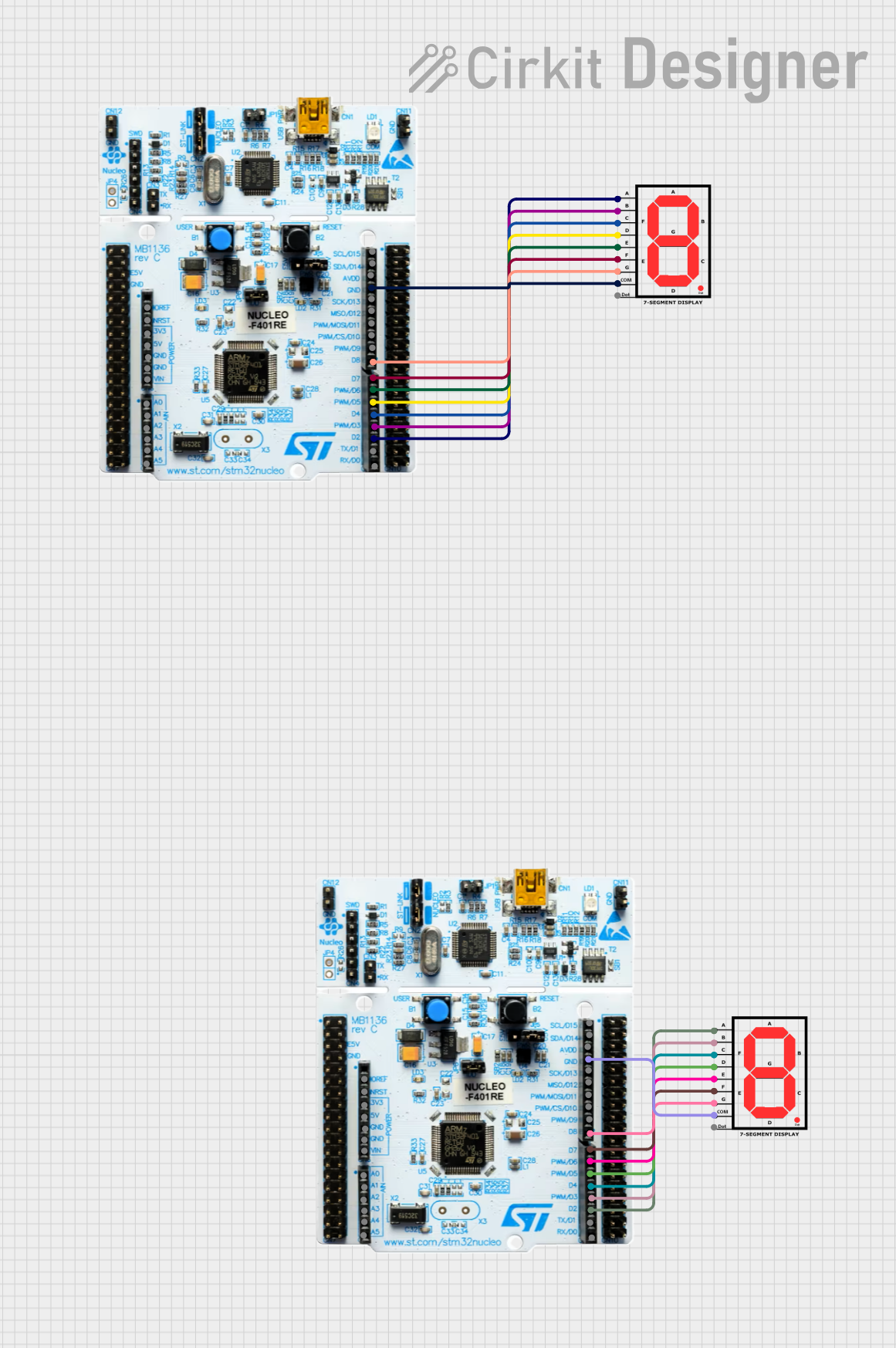
Circuit Connections
- Connect
VCCto the 5V pin on the Arduino. - Connect
GNDto the GND pin on the Arduino. - Connect segment pins (
A,B,C,D,E,F) to digital pins 2 through 7 on the Arduino. - Connect
D1andD2to digital pins 8 and 9, respectively.
Arduino Code
// Define segment pins
const int segmentPins[] = {2, 3, 4, 5, 6, 7}; // A, B, C, D, E, F
const int digitPins[] = {8, 9}; // D1, D2

// Segment patterns for digits 0-9
const byte digitPatterns[10] = {
  0b111111, // 0
  0b011000, // 1
  0b110110, // 2
  0b111100, // 3
  0b011001, // 4
  0b101101, // 5
  0b101111, // 6
  0b111000, // 7
  0b111111, // 8
  0b111101  // 9
};

void setup() {
  // Set segment and digit pins as outputs
  for (int i = 0; i < 6; i++) {
    pinMode(segmentPins[i], OUTPUT);
  }
  for (int i = 0; i < 2; i++) {
    pinMode(digitPins[i], OUTPUT);
  }
}

void loop() {
  // Display the number "12" on the display
  displayDigit(1, 0); // Display "1" on digit 1
  delay(5);           // Short delay for multiplexing
  displayDigit(2, 1); // Display "2" on digit 2
  delay(5);           // Short delay for multiplexing
}

// Function to display a digit on a specific position
void displayDigit(int number, int digit) {
  // Turn off all digits
  for (int i = 0; i < 2; i++) {
    digitalWrite(digitPins[i], LOW);
  }

  // Set segment pins based on the digit pattern
  for (int i = 0; i < 6; i++) {
    digitalWrite(segmentPins[i], (digitPatterns[number] >> i) & 0x01);
  }

  // Turn on the selected digit
  digitalWrite(digitPins[digit], HIGH);
}
Troubleshooting and FAQs
Common Issues
Display Not Turning On:
- Ensure the
VCCandGNDconnections are secure. - Verify that the power supply voltage is within the specified range (3.3V to 5V).
- Ensure the
Incorrect Digits Displayed:
- Check the wiring of the segment and digit pins.
- Verify that the microcontroller code matches the pin connections.
Dim Display:
- Ensure the current-limiting resistors are not too high.
- Check the power supply for sufficient current output.
Flickering Display:
- Adjust the multiplexing delay in the code to optimize refresh rate.
- Ensure all connections are stable and free from loose wires.
FAQs
Q: Can I use the GMT020 Display2 with a 3.3V microcontroller?
A: Yes, the display is compatible with both 3.3V and 5V systems. Ensure the current-limiting resistors are appropriately chosen.
Q: How do I control the brightness of the display?
A: Brightness can be controlled by adjusting the current through the segments or using PWM on the segment pins.
Q: Can I use this display for alphanumeric characters?
A: The GMT020 Display2 is primarily designed for numerical data. For alphanumeric characters, consider using a dot-matrix or alphanumeric display module.