Cirkit Designer
Your all-in-one circuit design IDE
Home /
Component Documentation
How to Use SparkFun Motor Driver TB6612FNG (v11): Examples, Pinouts, and Specs
Introduction
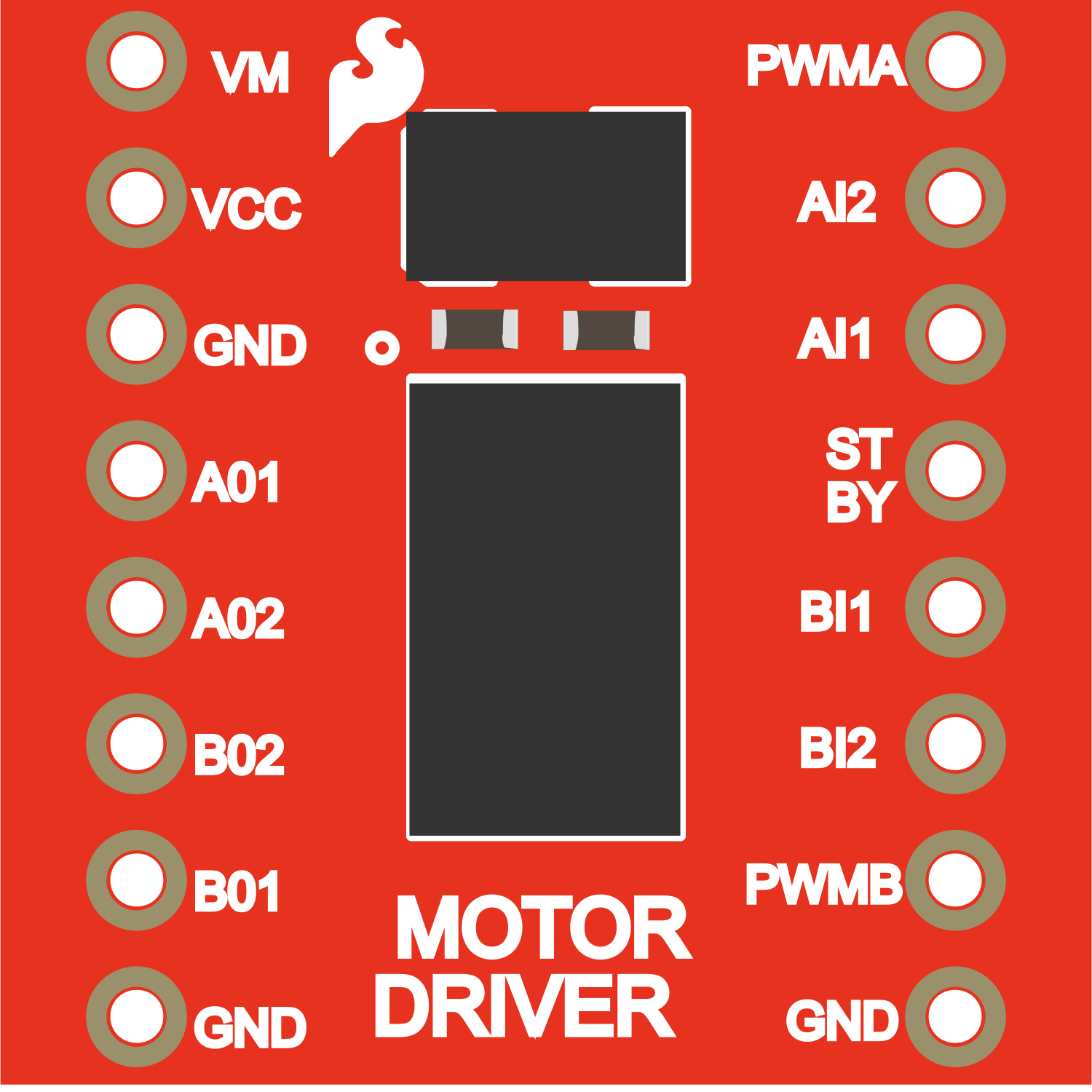
The SparkFun Motor Driver TB6612FNG (v11) is a versatile and efficient dual H-bridge motor driver capable of controlling two DC motors independently or one bipolar stepper motor. Its compact form factor and ease of use make it an excellent choice for small robotics projects, educational purposes, and hobbyist applications.
Explore Projects Built with SparkFun Motor Driver TB6612FNG (v11)
ESP32 Wi-Fi Controlled Dual DC Motor Driver System
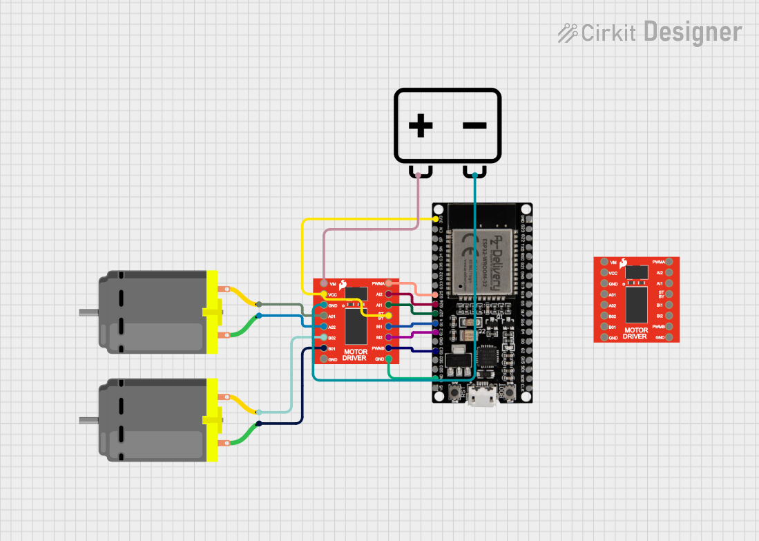
This circuit uses an ESP32 microcontroller to control two DC motors via a SparkFun Motor Driver TB6612FNG. The motor driver is powered by a 12V battery and receives control signals from the ESP32 to manage the speed and direction of the motors.
Arduino Nano Controlled Robot with Ultrasonic Sensor and Dual Motor Drivers
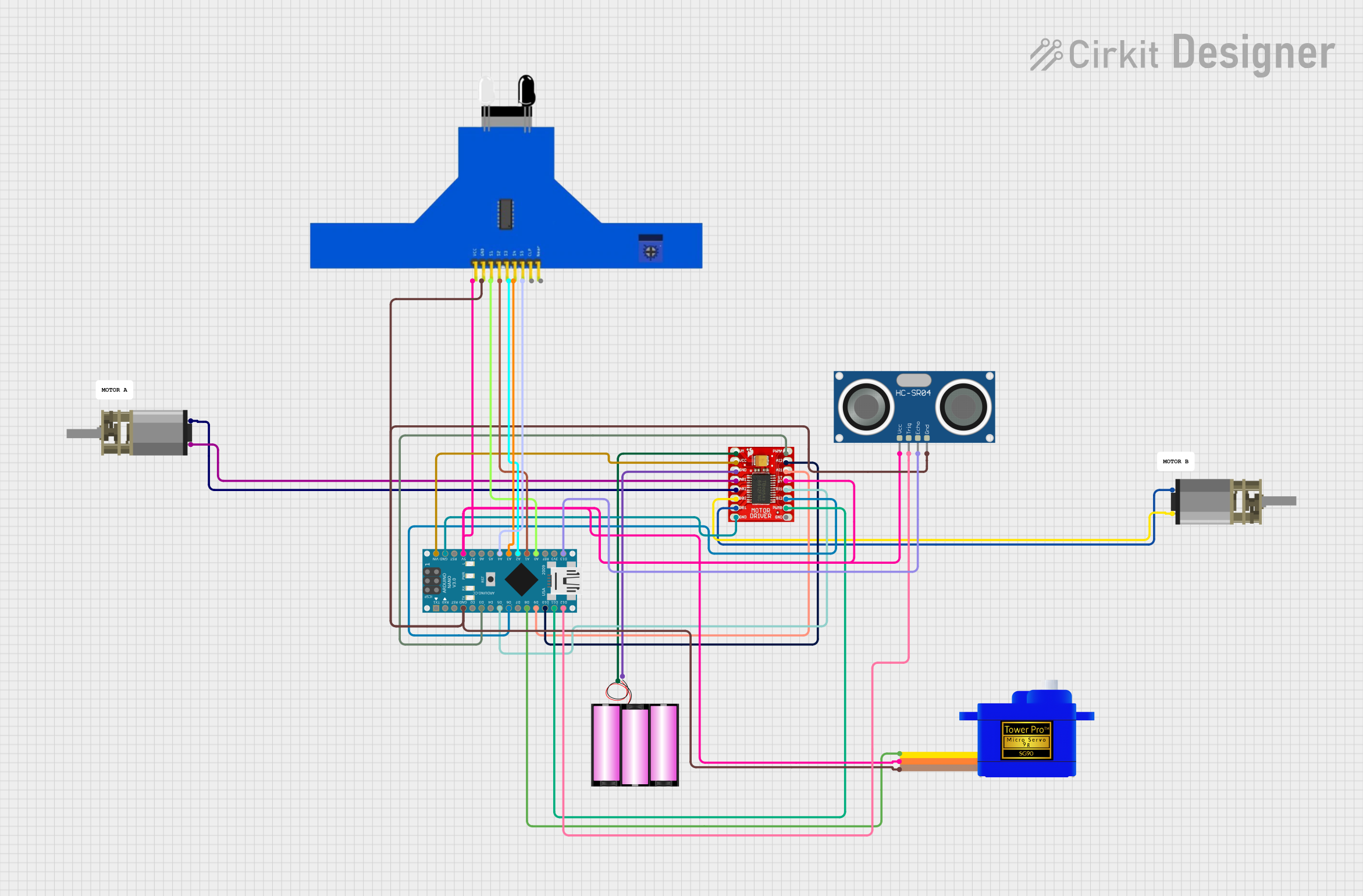
This circuit features an Arduino Nano microcontroller interfaced with a TB6612FNG motor driver to control two DC Mini Metal Gear Motors. It also includes an HC-SR04 Ultrasonic Sensor for distance measurement, a 5 channel IR sensor for line tracking, and a Servomotor SG90 for positioning tasks. The system is powered by a 12V battery, with the Arduino Nano managing sensor inputs and motor outputs to perform tasks such as navigation or automation.
Arduino UNO and Motor Driver Controlled Dual Motor System with LED Indicator
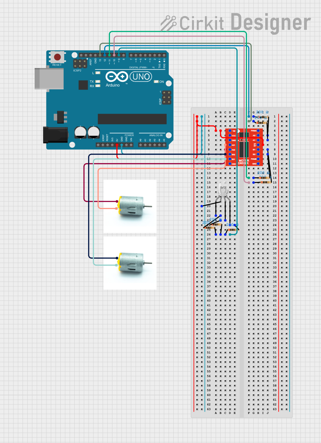
This circuit uses an Arduino UNO to control a motor driver (SparkFun TB6612FNG) and a four-pin LED. The Arduino provides power and control signals to the motor driver, which in turn drives two motors, while the LED is connected through resistors to various digital pins on the Arduino for color control.
Arduino-Controlled Dual Motor Driver with IR Sensing

This circuit controls two DC motors using a TB6612FNG motor driver, which is interfaced with an Arduino Mega 2560 microcontroller. The Arduino provides PWM signals to control the speed and direction of the motors. Multiple IR sensors are connected to the Arduino's analog inputs, likely for sensing the environment or for line-following capabilities in a robot.
Explore Projects Built with SparkFun Motor Driver TB6612FNG (v11)
ESP32 Wi-Fi Controlled Dual DC Motor Driver System
This circuit uses an ESP32 microcontroller to control two DC motors via a SparkFun Motor Driver TB6612FNG. The motor driver is powered by a 12V battery and receives control signals from the ESP32 to manage the speed and direction of the motors.
Arduino Nano Controlled Robot with Ultrasonic Sensor and Dual Motor Drivers
This circuit features an Arduino Nano microcontroller interfaced with a TB6612FNG motor driver to control two DC Mini Metal Gear Motors. It also includes an HC-SR04 Ultrasonic Sensor for distance measurement, a 5 channel IR sensor for line tracking, and a Servomotor SG90 for positioning tasks. The system is powered by a 12V battery, with the Arduino Nano managing sensor inputs and motor outputs to perform tasks such as navigation or automation.
Arduino UNO and Motor Driver Controlled Dual Motor System with LED Indicator
This circuit uses an Arduino UNO to control a motor driver (SparkFun TB6612FNG) and a four-pin LED. The Arduino provides power and control signals to the motor driver, which in turn drives two motors, while the LED is connected through resistors to various digital pins on the Arduino for color control.
Arduino-Controlled Dual Motor Driver with IR Sensing
This circuit controls two DC motors using a TB6612FNG motor driver, which is interfaced with an Arduino Mega 2560 microcontroller. The Arduino provides PWM signals to control the speed and direction of the motors. Multiple IR sensors are connected to the Arduino's analog inputs, likely for sensing the environment or for line-following capabilities in a robot.
Common Applications and Use Cases
- Driving small to medium DC motors
- Controlling a single bipolar stepper motor
- Robotics projects
- Educational platforms for learning motor control
- DIY projects requiring motor control
Technical Specifications
Key Technical Details
- Motor Supply Voltage (VM): 2.5V to 13.5V
- Logic Supply Voltage (VCC): 2.7V to 5.5V
- Output Current (continuous): 1.2A per channel
- Output Peak Current (non-repetitive): 3.2A
- Standby Control to Save Power
- Built-in Thermal Shutdown Circuit and Low Voltage Detecting Circuit
Pin Configuration and Descriptions
| Pin Number | Pin Name | Description |
|---|---|---|
| 1 | VM | Motor voltage supply, connects to the motor power source |
| 2 | VCC | Logic voltage supply, connects to the control board (e.g., Arduino) |
| 3 | GND | Ground pin |
| 4 | A01 | Motor A output 1 |
| 5 | A02 | Motor A output 2 |
| 6 | B01 | Motor B output 1 |
| 7 | B02 | Motor B output 2 |
| 8 | PWMA | PWM input for motor A speed control |
| 9 | AIN1 | Direction control for motor A |
| 10 | AIN2 | Direction control for motor A |
| 11 | STBY | Standby pin (active low) |
| 12 | BIN1 | Direction control for motor B |
| 13 | BIN2 | Direction control for motor B |
| 14 | PWMB | PWM input for motor B speed control |
Usage Instructions
How to Use the Component in a Circuit
Power Connections:
- Connect the motor power supply to the VM pin.
- Connect the logic power supply from the control board to the VCC pin.
- Ensure that the ground from the control board and the motor power supply are common and connected to the GND pin.
Motor Connections:
- Connect the two terminals of motor A to the A01 and A02 pins.
- Connect the two terminals of motor B to the B01 and B02 pins.
Control Connections:
- Connect the control inputs (AIN1, AIN2, BIN1, BIN2) to the digital outputs on the control board.
- Connect the PWM inputs (PWMA, PWMB) to the PWM-capable outputs on the control board for speed control.
- The STBY pin must be driven high to take the driver out of standby mode.
Important Considerations and Best Practices
- Ensure that the power supply voltage does not exceed the maximum ratings for VM and VCC.
- Use PWM signals for speed control to avoid sudden current spikes.
- Always put the driver into standby mode when not in use to save power.
- Provide adequate cooling if the driver is expected to handle currents near the maximum continuous rating.
Troubleshooting and FAQs
Common Issues Users Might Face
- Motor not running: Check power supply connections, ensure that the STBY pin is driven high, and verify that the control inputs are correctly configured.
- Overheating: Ensure that the current draw is within the limits and consider adding a heatsink or improving airflow around the driver.
Solutions and Tips for Troubleshooting
- Check Connections: Double-check all connections, including power, ground, and control signals.
- Test Power Supply: Verify that the power supply is providing the correct voltage and is capable of supplying sufficient current.
- Signal Integrity: Ensure that PWM and control signals are clean and free from noise.
Example Code for Arduino UNO
// Define the connections to the TB6612FNG
const int PWMA = 3; // PWM control for motor A
const int AIN1 = 4; // Direction control for motor A
const int AIN2 = 5; // Direction control for motor A
const int STBY = 6; // Standby

void setup() {
  // Set all the motor control pins to outputs
  pinMode(PWMA, OUTPUT);
  pinMode(AIN1, OUTPUT);
  pinMode(AIN2, OUTPUT);
  pinMode(STBY, OUTPUT);

  // Take the motor driver out of standby
  digitalWrite(STBY, HIGH);
}

void loop() {
  // Set motor A to spin in one direction
  digitalWrite(AIN1, HIGH);
  digitalWrite(AIN2, LOW);
  analogWrite(PWMA, 128); // Set speed (0 to 255)

  delay(1000); // Run for 1 second

  // Set motor A to spin in the opposite direction
  digitalWrite(AIN1, LOW);
  digitalWrite(AIN2, HIGH);
  analogWrite(PWMA, 128); // Set speed (0 to 255)

  delay(1000); // Run for 1 second

  // Stop the motor
  digitalWrite(AIN1, LOW);
  digitalWrite(AIN2, LOW);
  analogWrite(PWMA, 0); // Set speed to zero (motor off)

  delay(1000); // Wait for 1 second
}
This example demonstrates basic forward and reverse control of a motor connected to motor driver A. Adjust the analogWrite value between 0 and 255 to control the speed of the motor.