How to Use Motor Driver: Examples, Pinouts, and Specs
Introduction
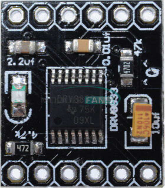
A motor driver is an essential electronic component designed to control the operation of motors by providing the required voltage and current. Manufactured by PAMEENCOS, this motor driver enables precise control of motor speed and direction, making it ideal for applications in robotics, automation, and other motor-driven systems. It acts as an interface between a microcontroller (or control system) and the motor, ensuring safe and efficient operation.
Explore Projects Built with Motor Driver


Explore Projects Built with Motor Driver
Common Applications and Use Cases
- Robotics: Controlling the movement of robotic arms, wheels, or actuators.
- Automation: Driving conveyor belts, pumps, or industrial machinery.
- Remote-controlled vehicles: Managing speed and direction of motors.
- DIY projects: Building motorized systems like drones, cars, or home automation devices.
Technical Specifications
The PAMEENCOS motor driver is designed to work with a wide range of DC motors and stepper motors. Below are the key technical details:
General Specifications
| Parameter | Value |
|---|---|
| Operating Voltage | 5V to 36V |
| Maximum Output Current | 2A per channel (continuous) |
| Peak Output Current | 3A per channel (short duration) |
| Number of Channels | 2 (dual H-bridge configuration) |
| Control Logic Voltage | 3.3V or 5V (compatible with most microcontrollers) |
| PWM Frequency | Up to 20 kHz |
| Motor Types Supported | DC motors, stepper motors |
| Operating Temperature | -20°C to 85°C |
Pin Configuration and Descriptions
The motor driver has the following pin layout:
Input Pins (Control Signals)
| Pin Name | Description |
|---|---|
| IN1 | Input signal to control motor 1 direction |
| IN2 | Input signal to control motor 1 direction |
| IN3 | Input signal to control motor 2 direction |
| IN4 | Input signal to control motor 2 direction |
| ENA | PWM input to control motor 1 speed |
| ENB | PWM input to control motor 2 speed |
Output Pins (Motor Connections)
| Pin Name | Description |
|---|---|
| OUT1 | Motor 1 terminal A |
| OUT2 | Motor 1 terminal B |
| OUT3 | Motor 2 terminal A |
| OUT4 | Motor 2 terminal B |
Power and Ground Pins
| Pin Name | Description |
|---|---|
| VCC | Power supply for the motor (5V to 36V) |
| GND | Ground connection |
| 5V | Logic voltage supply (optional, for 5V logic compatibility) |
Usage Instructions
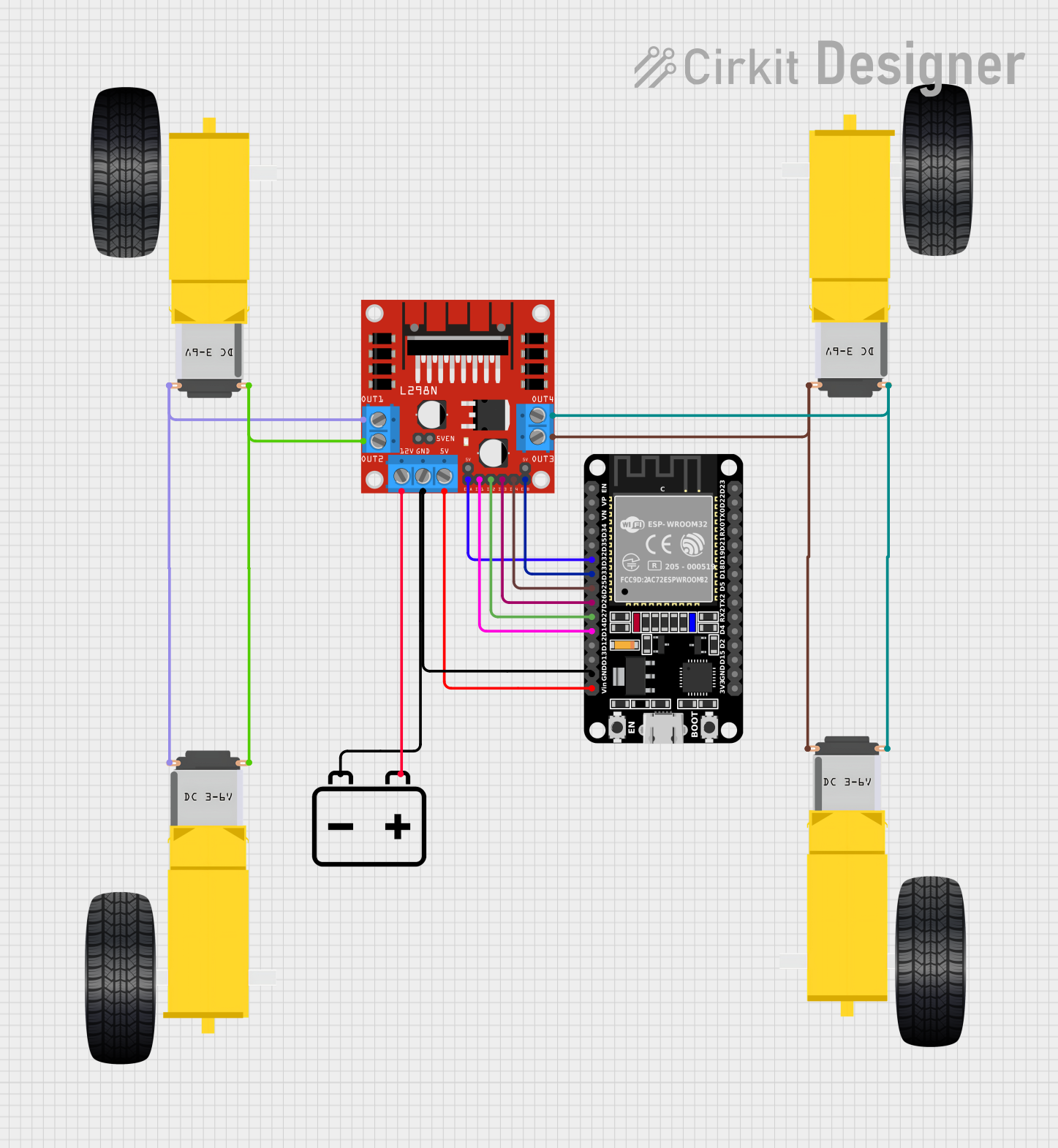
How to Use the Motor Driver in a Circuit
Connect Power Supply:
- Connect the motor power supply to the
VCCpin and ground to theGNDpin. - Ensure the power supply voltage matches the motor's operating voltage.
- Connect the motor power supply to the
Connect Motors:
- Attach the motor terminals to the
OUT1,OUT2(for motor 1) andOUT3,OUT4(for motor 2) pins.
- Attach the motor terminals to the
Connect Control Signals:
- Connect the control pins (
IN1,IN2,IN3,IN4,ENA,ENB) to the microcontroller's GPIO pins. - Use PWM signals on
ENAandENBto control motor speed.
- Connect the control pins (
Logic Voltage:
- If using a 5V logic microcontroller, connect the
5Vpin to the microcontroller's 5V output. - For 3.3V logic, ensure the motor driver is compatible without additional connections.
- If using a 5V logic microcontroller, connect the
Programming:
- Write code to send appropriate signals to the control pins for motor direction and speed.
Important Considerations and Best Practices
- Current Limitation: Ensure the motor's current draw does not exceed the motor driver's maximum current rating.
- Heat Dissipation: Use a heat sink or cooling mechanism if operating at high currents for extended periods.
- Power Supply: Use a stable and sufficient power supply to avoid voltage drops.
- Decoupling Capacitors: Add capacitors near the motor driver to reduce noise and voltage spikes.
Example Code for Arduino UNO
Below is an example code to control a DC motor using the PAMEENCOS motor driver:
// Define motor control pins
const int IN1 = 7;  // Motor 1 direction control pin
const int IN2 = 8;  // Motor 1 direction control pin
const int ENA = 9;  // Motor 1 speed control (PWM pin)

void setup() {
  // Set motor control pins as outputs
  pinMode(IN1, OUTPUT);
  pinMode(IN2, OUTPUT);
  pinMode(ENA, OUTPUT);
}

void loop() {
  // Rotate motor in one direction
  digitalWrite(IN1, HIGH);  // Set IN1 high
  digitalWrite(IN2, LOW);   // Set IN2 low
  analogWrite(ENA, 128);    // Set speed to 50% (PWM value: 128)

  delay(2000);              // Run for 2 seconds

  // Rotate motor in the opposite direction
  digitalWrite(IN1, LOW);   // Set IN1 low
  digitalWrite(IN2, HIGH);  // Set IN2 high
  analogWrite(ENA, 128);    // Maintain speed at 50%

  delay(2000);              // Run for 2 seconds

  // Stop the motor
  digitalWrite(IN1, LOW);   // Set IN1 low
  digitalWrite(IN2, LOW);   // Set IN2 low
  analogWrite(ENA, 0);      // Set speed to 0

  delay(2000);              // Wait for 2 seconds before repeating
}
Troubleshooting and FAQs
Common Issues and Solutions
Motor Not Running:
- Cause: Incorrect wiring or insufficient power supply.
- Solution: Double-check all connections and ensure the power supply matches the motor's requirements.
Motor Running in the Wrong Direction:
- Cause: Control signals (
IN1,IN2, etc.) are reversed. - Solution: Swap the logic levels of the control pins or reverse the motor connections.
- Cause: Control signals (
Overheating:
- Cause: Excessive current draw or insufficient cooling.
- Solution: Use a heat sink or reduce the motor's load.
PWM Signal Not Controlling Speed:
- Cause: Incorrect PWM frequency or improper connection to
ENA/ENB. - Solution: Verify the PWM signal and ensure it is connected to the correct pin.
- Cause: Incorrect PWM frequency or improper connection to
FAQs
Can this motor driver control stepper motors? Yes, it can control stepper motors by appropriately sequencing the control signals.
What happens if the motor draws more than 2A? The motor driver may overheat or shut down. Use a motor with a current rating within the driver's limits.
Is it compatible with 3.3V logic microcontrollers? Yes, the motor driver supports both 3.3V and 5V logic levels.
Can I use this motor driver for AC motors? No, this motor driver is designed for DC motors and stepper motors only.