
How to Use Adafruit MCP23017 STEMMA QT: Examples, Pinouts, and Specs
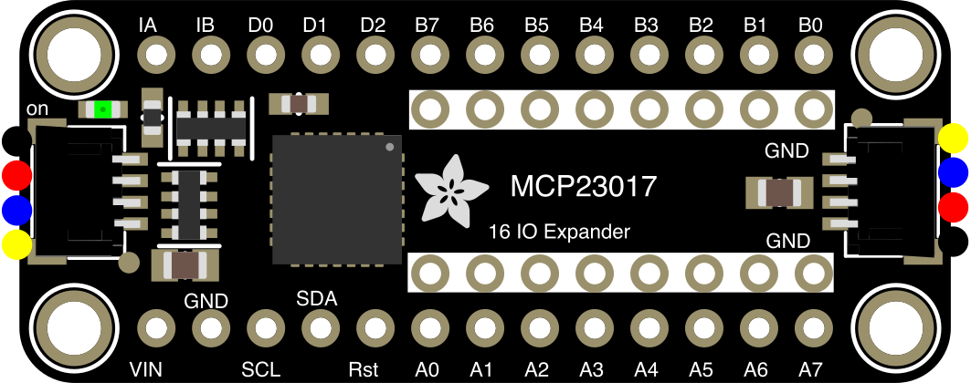
 Design with Adafruit MCP23017 STEMMA QT in Cirkit Designer
Introduction
The Adafruit MCP23017 STEMMA QT (Part ID: 5346) is a 16-channel I/O expander designed to provide additional GPIO pins for microcontrollers. It communicates via the I2C protocol, making it an excellent choice for projects requiring multiple input/output pins without consuming additional microcontroller resources. The inclusion of STEMMA QT connectors simplifies integration with other sensors and devices, enabling quick and solder-free prototyping.
Explore Projects Built with Adafruit MCP23017 STEMMA QT
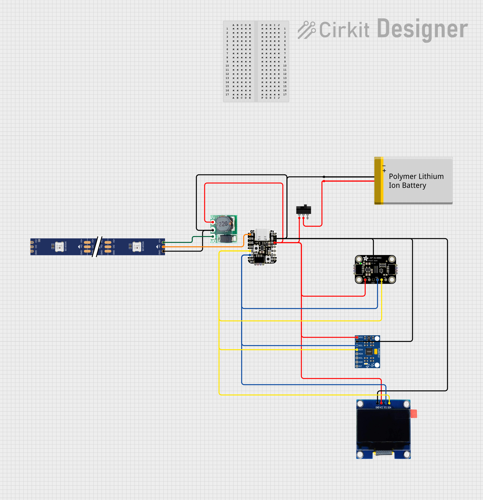 Open Project in Cirkit Designer
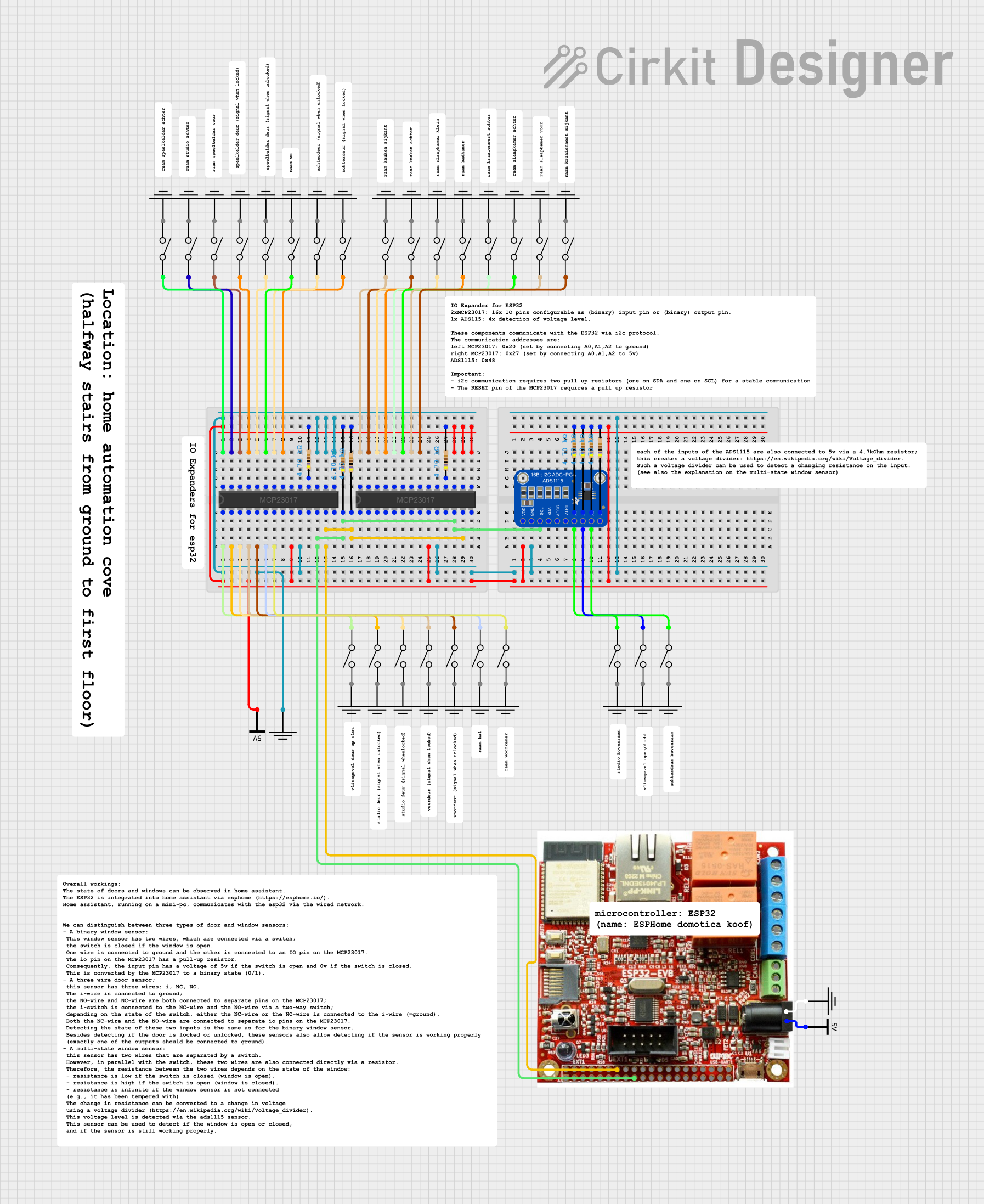 Open Project in Cirkit Designer
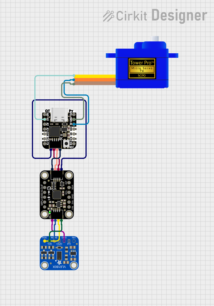 Open Project in Cirkit Designer
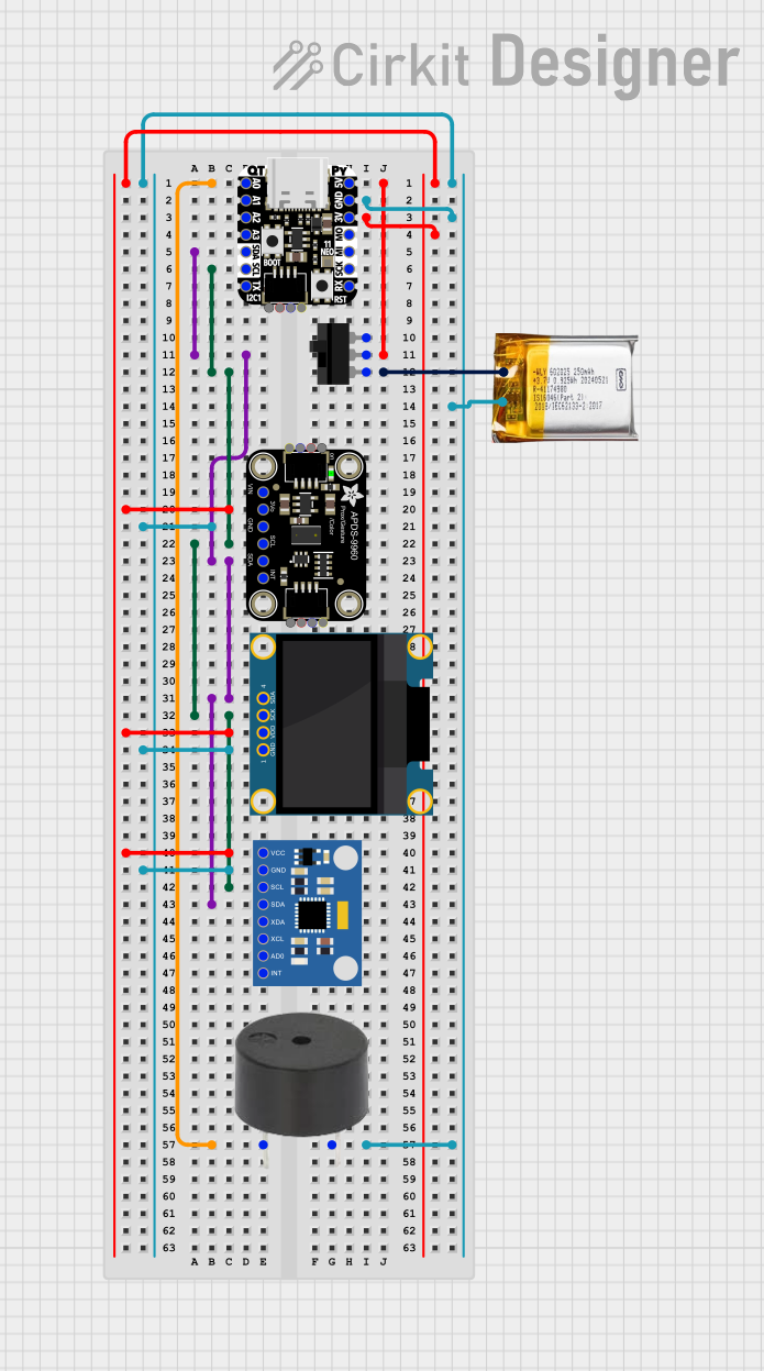 Open Project in Cirkit Designer
Explore Projects Built with Adafruit MCP23017 STEMMA QT
Open Project in Cirkit DesignerOpen Project in Cirkit DesignerOpen Project in Cirkit DesignerOpen Project in Cirkit DesignerCommon Applications and Use Cases
- Expanding GPIO capabilities of microcontrollers like Arduino, Raspberry Pi, or ESP32.
- Driving LEDs, relays, or other output devices.
- Reading multiple buttons, switches, or sensors.
- Building control panels or keypads.
- Projects requiring modular and solder-free connections.
Technical Specifications
Key Technical Details
- I/O Channels: 16 GPIO pins (organized as two 8-bit ports: GPA and GPB).
- Communication Protocol: I2C.
- Operating Voltage: 1.8V to 5.5V.
- Maximum Current per Pin: 25mA (sink/source).
- I2C Address Range: Configurable from 0x20 to 0x27 (up to 8 devices on the same I2C bus).
- Pull-up Resistors: Internal 100kΩ (configurable).
- Interrupt Pins: Two interrupt outputs (INTA and INTB) for event-driven designs.
- STEMMA QT Connectors: Two connectors for daisy-chaining I2C devices.
- Dimensions: 25.5mm x 17.5mm x 4.5mm (excluding connectors).
Pin Configuration and Descriptions
The MCP23017 STEMMA QT has the following pin layout:
GPIO Pins
| Pin Name | Description |
|---|---|
| GPA0-GPA7 | General-purpose I/O pins (Port A). |
| GPB0-GPB7 | General-purpose I/O pins (Port B). |
Power and Control Pins
| Pin Name | Description |
|---|---|
| VIN | Power input (1.8V to 5.5V). |
| GND | Ground. |
| SCL | I2C clock line. |
| SDA | I2C data line. |
| INTA | Interrupt output for Port A. |
| INTB | Interrupt output for Port B. |
STEMMA QT Connectors
| Connector | Description |
|---|---|
| STEMMA QT | Two connectors for chaining I2C devices. |
Usage Instructions
How to Use the MCP23017 in a Circuit
- Power the Module: Connect the VIN pin to a 3.3V or 5V power source and GND to ground.
- Connect I2C Lines: Attach the SCL and SDA pins to the corresponding I2C pins on your microcontroller.
- Set the I2C Address: Configure the address using the three address pins (A0, A1, A2). Leave them floating or connect to GND/VIN to set the desired address.
- Connect GPIO Devices: Attach LEDs, buttons, or other devices to the GPA and GPB pins.
- Install Libraries: Use the Adafruit MCP23017 library for easy integration with Arduino or CircuitPython.
Important Considerations and Best Practices
- Pull-up Resistors: Ensure proper pull-up resistors are present on the I2C lines if not already included in your setup.
- Interrupts: Use the INTA and INTB pins for event-driven designs to avoid constant polling.
- Voltage Compatibility: Ensure all connected devices operate within the MCP23017's voltage range.
- Daisy-Chaining: When using multiple MCP23017 modules, configure unique I2C addresses for each.
Example Code for Arduino UNO
Below is an example of how to use the MCP23017 with an Arduino UNO to toggle an LED connected to GPA0:
#include <Wire.h>
#include "Adafruit_MCP23X17.h"

// Create an MCP23017 object
Adafruit_MCP23X17 mcp;

void setup() {
  Serial.begin(9600);
  while (!Serial) {
    delay(10); // Wait for Serial Monitor to open
  }

  // Initialize the MCP23017
  if (!mcp.begin_I2C()) {
    Serial.println("Failed to initialize MCP23017. Check connections!");
    while (1);
  }
  Serial.println("MCP23017 initialized!");

  // Set GPA0 as an output pin
  mcp.pinMode(0, OUTPUT);
}

void loop() {
  // Toggle the LED on GPA0
  mcp.digitalWrite(0, HIGH); // Turn LED on
  delay(500);                // Wait 500ms
  mcp.digitalWrite(0, LOW);  // Turn LED off
  delay(500);                // Wait 500ms
}
Troubleshooting and FAQs
Common Issues and Solutions
MCP23017 Not Detected on I2C Bus:
- Ensure the I2C address is correctly configured.
- Verify the SCL and SDA connections.
- Check for proper pull-up resistors on the I2C lines.
GPIO Pins Not Responding:
- Confirm the pin mode (input/output) is correctly set in the code.
- Check for loose or incorrect wiring.
Interrupts Not Triggering:
- Ensure the interrupt pins (INTA/INTB) are connected to the microcontroller.
- Verify the interrupt configuration in the code.
Multiple MCP23017 Modules Not Working:
- Ensure each module has a unique I2C address.
- Check for address conflicts with other I2C devices.
FAQs
Q: Can I use the MCP23017 with 3.3V microcontrollers?
A: Yes, the MCP23017 is compatible with both 3.3V and 5V systems.
Q: How many MCP23017 modules can I connect to a single I2C bus?
A: Up to 8 modules can be connected by configuring unique I2C addresses.
Q: Do I need external pull-up resistors for the GPIO pins?
A: No, the MCP23017 has internal pull-up resistors, but you can enable or disable them as needed.
Q: Can I use the STEMMA QT connectors with other Adafruit devices?
A: Yes, the STEMMA QT connectors are designed for seamless integration with other Adafruit STEMMA QT-compatible devices.