How to Use 4026: Examples, Pinouts, and Specs
Introduction
The 4026 is a versatile decade counter IC that counts from 0 to 9 and is widely used in digital electronics. It features a binary-coded decimal (BCD) output and an integrated 7-segment display driver, making it ideal for applications requiring numerical displays. The IC can be cascaded to count beyond ten, enabling its use in more complex counting systems.
Explore Projects Built with 4026


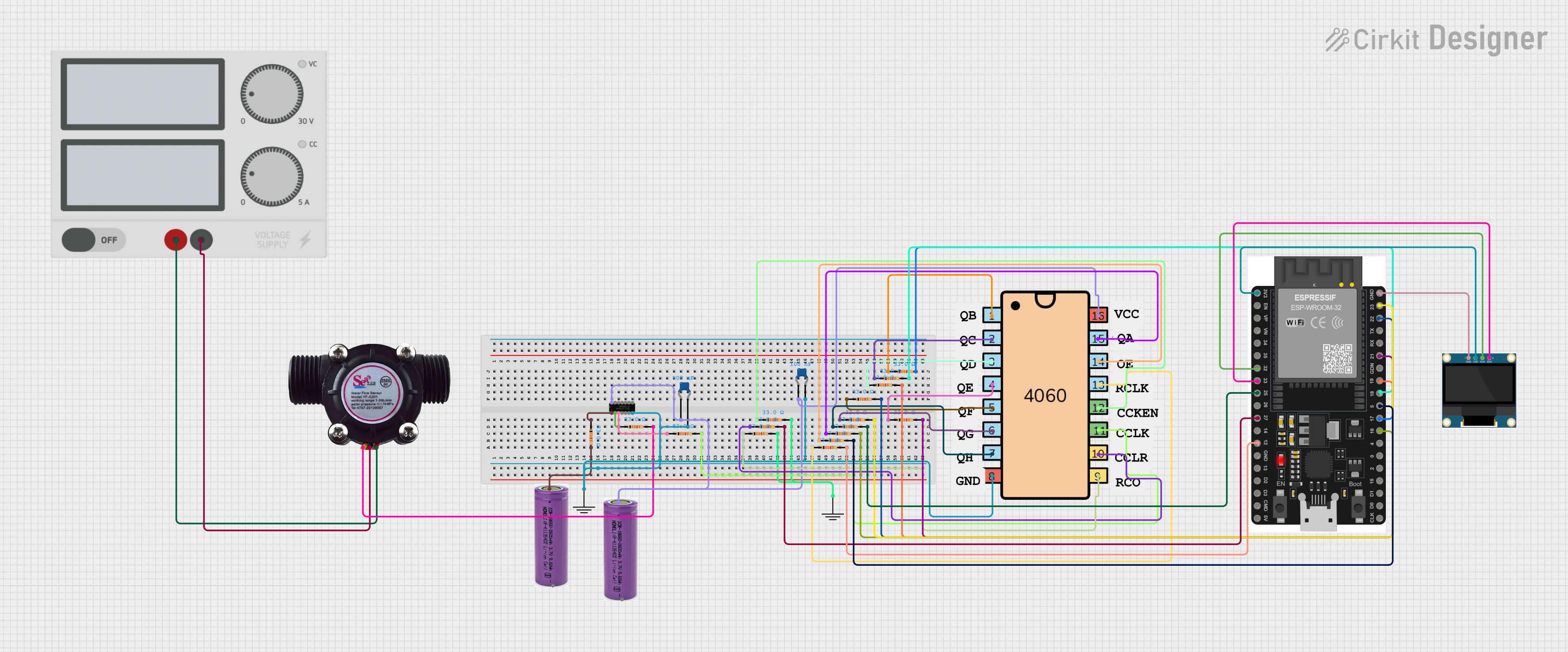
Explore Projects Built with 4026
Common Applications
- Digital clocks
- Frequency counters
- Event counters
- Digital meters
- Scoreboards
Technical Specifications
The 4026 IC is designed to operate efficiently in a variety of digital counting and display applications. Below are its key technical specifications:
| Parameter | Value |
|---|---|
| Supply Voltage (Vcc) | 3V to 15V |
| Maximum Output Current | 20mA per segment |
| Operating Temperature | -40°C to +85°C |
| Maximum Clock Frequency | 6 MHz (typical) |
| Logic Type | CMOS |
| Display Type Supported | Common Cathode 7-Segment |
Pin Configuration and Descriptions
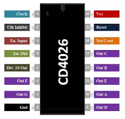
The 4026 IC has 16 pins, each serving a specific function. Below is the pinout and description:
| Pin Number | Pin Name | Description |
|---|---|---|
| 1 | Clock (CLK) | Input pin for clock pulses; increments the counter on each rising edge. |
| 2 | Clock Inhibit (CI) | Disables the clock input when HIGH; counter does not increment. |
| 3 | Display Enable (DE) | Enables the 7-segment display when HIGH. |
| 4 | Unused | Not connected internally; leave unconnected or grounded. |
| 5 | Carry Out (CO) | Outputs a pulse when the count resets to 0; used for cascading multiple ICs. |
| 6 | a | Segment "a" output for the 7-segment display. |
| 7 | b | Segment "b" output for the 7-segment display. |
| 8 | Vss (GND) | Ground pin. |
| 9 | c | Segment "c" output for the 7-segment display. |
| 10 | d | Segment "d" output for the 7-segment display. |
| 11 | e | Segment "e" output for the 7-segment display. |
| 12 | f | Segment "f" output for the 7-segment display. |
| 13 | g | Segment "g" output for the 7-segment display. |
| 14 | Display Enable Out | Outputs a signal to enable the next IC in a cascaded configuration. |
| 15 | Reset (RST) | Resets the counter to 0 when HIGH. |
| 16 | Vdd (Vcc) | Positive power supply pin. |
Usage Instructions
The 4026 IC is straightforward to use in digital circuits. Below are the steps and considerations for integrating it into your project:
Basic Circuit Setup
- Power Supply: Connect pin 16 (Vcc) to a positive voltage source (3V to 15V) and pin 8 (GND) to ground.
- Clock Input: Provide clock pulses to pin 1 (CLK) to increment the counter. Use a debounced switch or a microcontroller for precise clock signals.
- 7-Segment Display: Connect the segment output pins (6, 7, 9, 10, 11, 12, 13) to the corresponding segments of a common cathode 7-segment display.
- Reset Function: Use pin 15 (RST) to reset the counter to 0. This pin should be momentarily set HIGH to reset.
- Display Enable: Ensure pin 3 (DE) is HIGH to activate the 7-segment display.
Cascading Multiple 4026 ICs
To count beyond 9, cascade multiple 4026 ICs:
- Connect the Carry Out (pin 5) of the first IC to the Clock (pin 1) of the next IC.
- Repeat this for additional ICs as needed.
Example: Connecting to an Arduino UNO
The 4026 can be easily interfaced with an Arduino UNO for generating clock pulses and controlling the display. Below is an example code snippet:
// Example: Using Arduino UNO to control a 4026 IC
const int clockPin = 2;  // Arduino pin connected to 4026 CLK (pin 1)
const int resetPin = 3;  // Arduino pin connected to 4026 RST (pin 15)

void setup() {
  pinMode(clockPin, OUTPUT);  // Set clock pin as output
  pinMode(resetPin, OUTPUT);  // Set reset pin as output

  digitalWrite(clockPin, LOW);  // Initialize clock pin to LOW
  digitalWrite(resetPin, LOW);  // Initialize reset pin to LOW
}

void loop() {
  // Generate a clock pulse
  digitalWrite(clockPin, HIGH);  // Set clock pin HIGH
  delay(100);                    // Wait for 100ms
  digitalWrite(clockPin, LOW);   // Set clock pin LOW
  delay(100);                    // Wait for 100ms

  // Reset the counter (optional)
  // Uncomment the following lines to reset the counter
  /*
  digitalWrite(resetPin, HIGH);  // Set reset pin HIGH
  delay(10);                     // Wait for 10ms
  digitalWrite(resetPin, LOW);   // Set reset pin LOW
  */
}
Best Practices
- Use current-limiting resistors (220Ω to 1kΩ) between the segment outputs and the 7-segment display to prevent damage.
- Debounce mechanical switches used for clock input to avoid erratic counting.
- Ensure proper grounding and decoupling capacitors near the IC for stable operation.
Troubleshooting and FAQs
Common Issues
The 7-segment display does not light up.
- Ensure the Display Enable (DE) pin is HIGH.
- Check the connections between the segment output pins and the display.
- Verify that the display is a common cathode type.
The counter does not increment.
- Confirm that clock pulses are being provided to the Clock (CLK) pin.
- Check if the Clock Inhibit (CI) pin is LOW; if HIGH, the clock input is disabled.
The counter resets unexpectedly.
- Ensure the Reset (RST) pin is not floating; it should be LOW during normal operation.
- Check for noise or glitches on the Reset pin.
The IC overheats.
- Verify that the segment output current does not exceed 20mA per segment.
- Use appropriate current-limiting resistors.
FAQs
Q: Can I use a common anode 7-segment display with the 4026?
A: No, the 4026 is designed to work with common cathode displays only.
Q: How can I count beyond 9?
A: Cascade multiple 4026 ICs by connecting the Carry Out (CO) pin of one IC to the Clock (CLK) pin of the next.
Q: What is the maximum clock frequency for the 4026?
A: The typical maximum clock frequency is 6 MHz, but this may vary depending on the supply voltage and operating conditions.
By following this documentation, you can effectively integrate the 4026 IC into your digital counting and display projects.