How to Use Bus Servo Driver Board for Seeed Studio XIAO: Examples, Pinouts, and Specs
Introduction
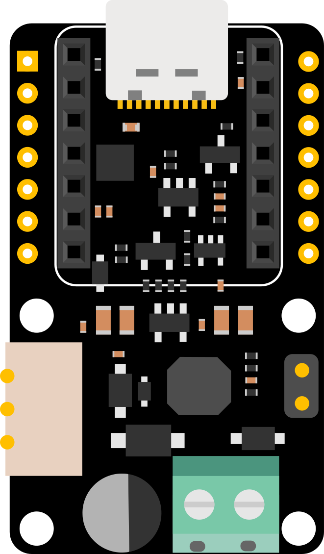
The Bus Servo Driver Board for Seeed Studio XIAO is a specialized driver board designed to control multiple servo motors efficiently using a single microcontroller. It is fully compatible with the Seeed Studio XIAO platform, making it an excellent choice for robotics, automation, and other projects requiring precise motor control. This board simplifies the integration and management of servo motors, enabling users to focus on their application rather than complex wiring or control logic.
Explore Projects Built with Bus Servo Driver Board for Seeed Studio XIAO

Explore Projects Built with Bus Servo Driver Board for Seeed Studio XIAO
Common Applications and Use Cases
- Robotics projects requiring multiple servo motors
- Automation systems for industrial or home use
- Animatronics and motion control systems
- Educational projects for learning servo motor control
- Prototyping and testing of servo-based mechanisms
Technical Specifications
The Bus Servo Driver Board is designed to provide reliable and efficient control of servo motors. Below are its key technical details:
Key Specifications
| Parameter | Value |
|---|---|
| Input Voltage | 5V (via USB-C or external power) |
| Servo Voltage Range | 4.8V to 6V |
| Communication Protocol | I2C |
| Number of Servo Ports | Up to 8 |
| Microcontroller Support | Seeed Studio XIAO (all variants) |
| Dimensions | 40mm x 30mm x 10mm |
| Connector Type | JST-SH 4-pin for servos |
Pin Configuration and Descriptions
The Bus Servo Driver Board features a simple pin layout for easy integration with the Seeed Studio XIAO. Below is the pin configuration:
Seeed Studio XIAO Pin Mapping
| Pin on XIAO | Function | Description |
|---|---|---|
| D0 (SDA) | I2C Data Line (SDA) | Used for I2C communication with servos |
| D1 (SCL) | I2C Clock Line (SCL) | Used for I2C communication with servos |
| 5V | Power Supply for Servos | Provides power to connected servos |
| GND | Ground | Common ground for the circuit |
Servo Connector Pinout (JST-SH 4-pin)
| Pin Number | Function | Description |
|---|---|---|
| 1 | VCC | Power supply for the servo (4.8V-6V) |
| 2 | GND | Ground |
| 3 | I2C Data (SDA) | Data line for servo communication |
| 4 | I2C Clock (SCL) | Clock line for servo communication |
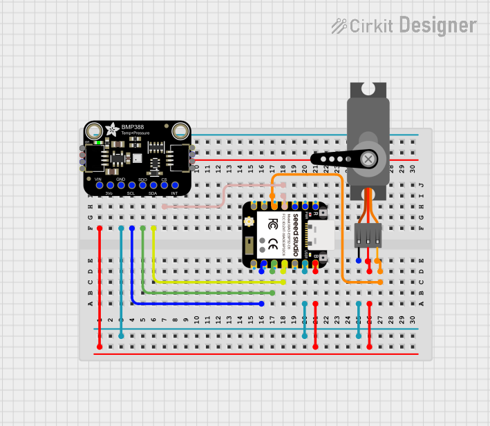
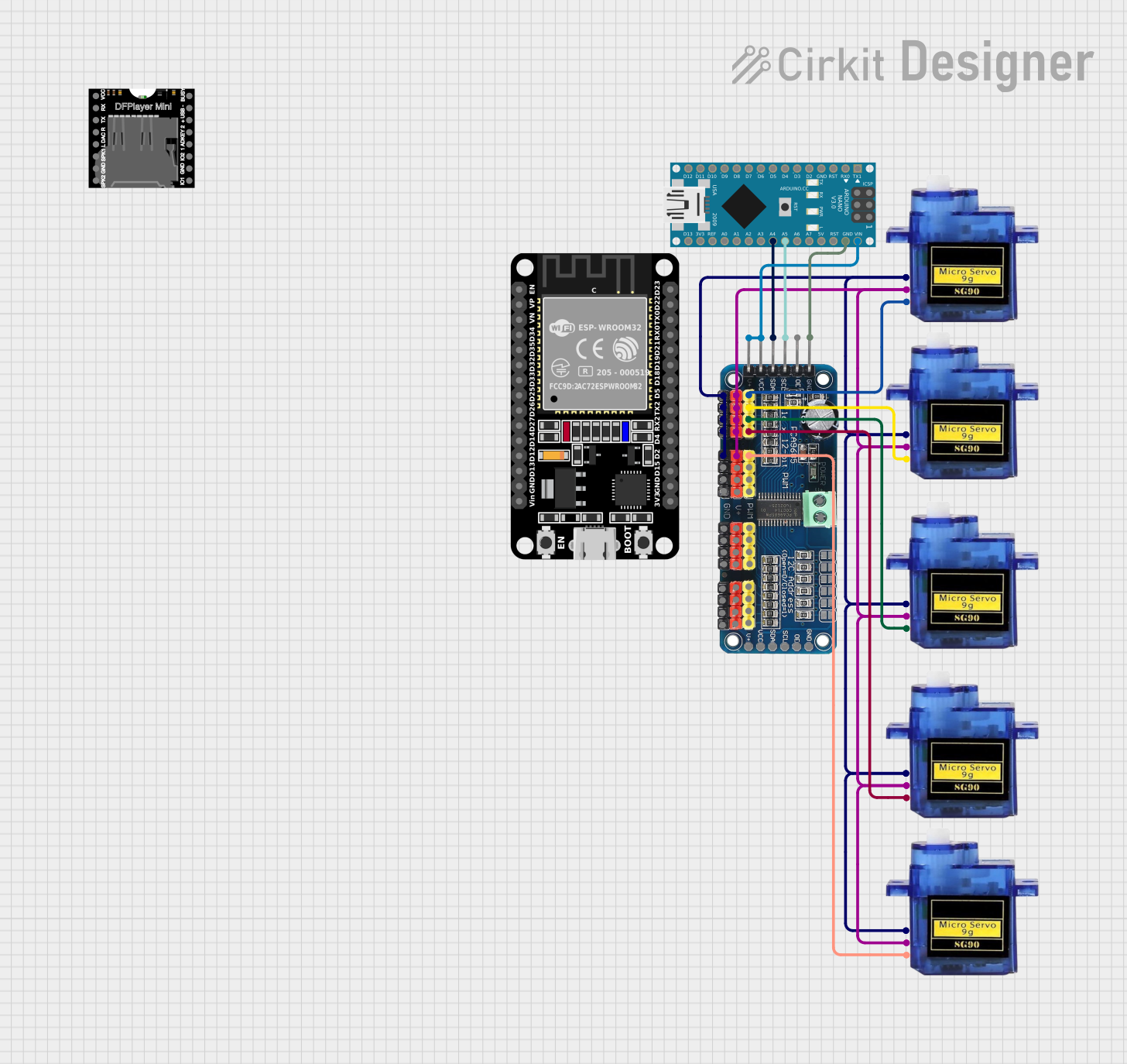
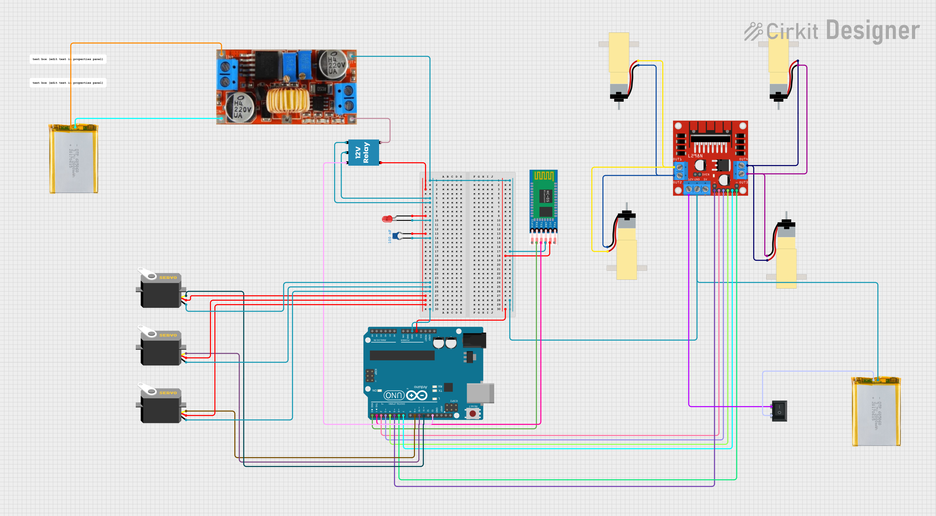
Usage Instructions
How to Use the Component in a Circuit
- Connect the Seeed Studio XIAO: Mount the XIAO microcontroller onto the Bus Servo Driver Board.
- Power the Board: Provide power to the board using a USB-C cable or an external 5V power source.
- Connect Servos: Attach up to 8 servos to the JST-SH 4-pin connectors on the board.
- Establish I2C Communication: Ensure the XIAO's SDA and SCL pins are correctly configured for I2C communication.
- Upload Code: Use the Arduino IDE or other compatible platforms to upload your servo control code to the XIAO.
Important Considerations and Best Practices
- Power Supply: Ensure the power supply can handle the combined current draw of all connected servos.
- Servo Compatibility: Verify that your servos operate within the 4.8V-6V range.
- I2C Addressing: If using multiple boards, ensure each board has a unique I2C address.
- Cable Management: Use appropriate cable lengths to avoid signal interference or power loss.
Example Code for Arduino UNO-Compatible XIAO
Below is an example code snippet to control a servo using the Bus Servo Driver Board:
#include <Wire.h>
#include <Servo.h>

// Define the I2C address of the servo driver board
#define SERVO_DRIVER_ADDR 0x40

Servo myServo; // Create a Servo object

void setup() {
  Wire.begin(); // Initialize I2C communication
  myServo.attach(0); // Attach servo to pin 0 on the driver board

  // Set up the servo driver board (if required by your specific board)
  Wire.beginTransmission(SERVO_DRIVER_ADDR);
  // Example: Send initialization commands to the board
  Wire.endTransmission();

  Serial.begin(9600); // Initialize serial communication for debugging
}

void loop() {
  for (int angle = 0; angle <= 180; angle += 10) {
    myServo.write(angle); // Move servo to the specified angle
    delay(500); // Wait for the servo to reach the position
  }

  for (int angle = 180; angle >= 0; angle -= 10) {
    myServo.write(angle); // Move servo back to the starting position
    delay(500); // Wait for the servo to reach the position
  }
}
Troubleshooting and FAQs
Common Issues and Solutions
Servos Not Responding
- Cause: Incorrect I2C wiring or address mismatch.
- Solution: Verify the SDA and SCL connections and ensure the correct I2C address is used in the code.
Power Issues
- Cause: Insufficient power supply for the servos.
- Solution: Use a power supply capable of providing sufficient current for all connected servos.
Servo Jitter
- Cause: Electrical noise or insufficient power.
- Solution: Use decoupling capacitors and ensure a stable power source.
Overheating
- Cause: Prolonged operation at high loads.
- Solution: Allow the servos to cool down periodically and avoid overloading.
FAQs
Q: Can I use this board with non-XIAO microcontrollers?
A: While designed for XIAO, the board can work with other microcontrollers that support I2C communication, but additional wiring may be required.
Q: How many servos can I control simultaneously?
A: The board supports up to 8 servos, provided the power supply can handle the total current draw.
Q: Can I daisy-chain multiple boards?
A: Yes, but ensure each board has a unique I2C address to avoid communication conflicts.
Q: What is the maximum servo angle supported?
A: The maximum angle depends on the servo model, but most standard servos support 0° to 180°.