How to Use XL4015 Step Down 5-32V: Examples, Pinouts, and Specs
Introduction
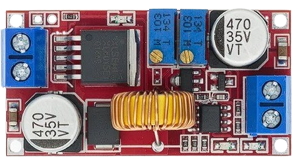
The XL4015 Step Down 5-32V is a high-performance DC-DC buck converter designed to step down voltage from a higher input level (5-32V) to a lower, adjustable output voltage. It is widely used in applications requiring efficient power conversion, such as battery charging, LED drivers, and powering microcontrollers or other low-voltage devices. With its adjustable output voltage and current capabilities, the XL4015 is a versatile and reliable choice for a variety of electronic projects.
Explore Projects Built with XL4015 Step Down 5-32V


Explore Projects Built with XL4015 Step Down 5-32V
Common Applications and Use Cases
- Powering microcontrollers (e.g., Arduino, Raspberry Pi) from higher voltage sources
- Battery charging circuits
- LED lighting systems
- Solar power systems
- General-purpose voltage regulation in electronic projects
Technical Specifications
The XL4015 Step Down 5-32V is designed for high efficiency and flexibility. Below are its key technical specifications:
| Parameter | Value |
|---|---|
| Input Voltage Range | 5V to 32V |
| Output Voltage Range | 0.8V to 30V (adjustable) |
| Maximum Output Current | 5A (with proper heat dissipation) |
| Output Power | Up to 75W |
| Efficiency | Up to 96% |
| Switching Frequency | 180 kHz |
| Operating Temperature | -40°C to +85°C |
| Dimensions | 51mm x 26mm x 14mm |
Pin Configuration and Descriptions
The XL4015 module typically has the following pin layout:
| Pin Name | Description |
|---|---|
| VIN | Input voltage pin (connect to a DC source between 5V and 32V). |
| VOUT | Output voltage pin (provides the stepped-down voltage). |
| GND | Ground pin (common ground for input and output). |
| ADJ | Adjustment pin (used to set the output voltage and current via onboard potentiometers). |
Usage Instructions
How to Use the XL4015 in a Circuit
Connect the Input Voltage:
- Connect the VIN pin to a DC power source (e.g., a battery or power supply) within the range of 5V to 32V.
- Connect the GND pin to the ground of the power source.
Connect the Output Load:
- Connect the VOUT pin to the positive terminal of your load (e.g., a microcontroller, LED, or motor).
- Connect the GND pin to the ground of your load.
Adjust the Output Voltage and Current:
- Use the onboard potentiometers to adjust the output voltage and current:
- The voltage adjustment potentiometer allows you to set the desired output voltage.
- The current adjustment potentiometer limits the maximum output current to protect your load.
- Use the onboard potentiometers to adjust the output voltage and current:
Verify the Output:
- Use a multimeter to measure the output voltage and current to ensure they match your requirements.
Important Considerations and Best Practices
- Heat Dissipation: The XL4015 can handle up to 5A of current, but proper heat dissipation (e.g., a heatsink or active cooling) is required for high-power applications.
- Input Voltage: Ensure the input voltage is at least 1.5V higher than the desired output voltage for proper operation.
- Polarity: Double-check the polarity of your connections to avoid damaging the module.
- Load Protection: Use the current adjustment feature to prevent overcurrent damage to your load.
Example: Using the XL4015 with an Arduino UNO
The XL4015 can be used to power an Arduino UNO from a 12V power source. Below is an example setup:
- Connect the 12V power source to the VIN and GND pins of the XL4015.
- Adjust the output voltage to 5V using the voltage adjustment potentiometer.
- Connect the VOUT pin to the 5V pin of the Arduino UNO and the GND pin to the Arduino's GND.
Here is a simple Arduino code example to blink an LED, powered by the XL4015:
// Simple LED Blink Example
// Ensure the XL4015 is set to output 5V before connecting to the Arduino UNO.

const int ledPin = 13; // Pin connected to the onboard LED

void setup() {
  pinMode(ledPin, OUTPUT); // Set the LED pin as an output
}

void loop() {
  digitalWrite(ledPin, HIGH); // Turn the LED on
  delay(1000);                // Wait for 1 second
  digitalWrite(ledPin, LOW);  // Turn the LED off
  delay(1000);                // Wait for 1 second
}
Troubleshooting and FAQs
Common Issues and Solutions
No Output Voltage:
- Cause: Incorrect input connections or insufficient input voltage.
- Solution: Verify the input voltage is within the 5-32V range and check the polarity of the connections.
Output Voltage Not Adjustable:
- Cause: Faulty potentiometer or incorrect adjustment procedure.
- Solution: Turn the voltage adjustment potentiometer slowly and check the output with a multimeter.
Overheating:
- Cause: High current draw without proper heat dissipation.
- Solution: Attach a heatsink to the XL4015 module or use active cooling (e.g., a fan).
Load Not Powering On:
- Cause: Output current limit set too low.
- Solution: Adjust the current limit potentiometer to match the load's requirements.
FAQs
Q: Can the XL4015 be used to charge batteries?
A: Yes, the XL4015 is suitable for charging batteries. Ensure the output voltage and current are set according to the battery's specifications.
Q: What is the maximum input voltage for the XL4015?
A: The maximum input voltage is 32V. Exceeding this limit may damage the module.
Q: Can I use the XL4015 to power a Raspberry Pi?
A: Yes, the XL4015 can step down voltage to 5V to power a Raspberry Pi. Ensure the output current is sufficient for the Raspberry Pi model you are using.
Q: How do I know if the module is overheating?
A: If the module becomes too hot to touch or shuts down unexpectedly, it may be overheating. Use a heatsink or fan to improve heat dissipation.