Cirkit Designer Logo
Cirkit Designer
Your all-in-one circuit design IDE
Home / 
Component Documentation

How to Use RS232 module: Examples, Pinouts, and Specs

Image of RS232 module
Cirkit Designer LogoDesign with RS232 module in Cirkit Designer

Introduction

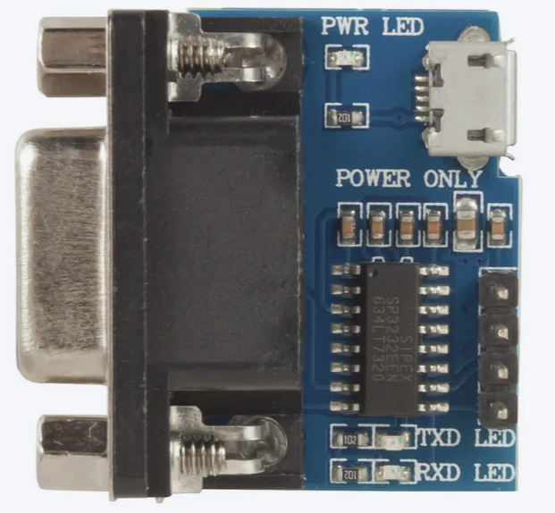
The RS232 module is a device designed to enable serial communication between a computer and peripheral devices using the RS232 standard. It serves as an interface that converts signals from a computer's serial port to a format compatible with devices such as modems, printers, microcontrollers, and other serial devices. The RS232 standard is widely used in industrial and embedded systems due to its simplicity and reliability.

Explore Projects Built with RS232 module

Use Cirkit Designer to design, explore, and prototype these projects online. Some projects support real-time simulation. Click "Open Project" to start designing instantly!
Cellular-Enabled IoT Device with Real-Time Clock and Power Management
Image of LRCM PHASE 2 BASIC: A project utilizing RS232 module in a practical application
This circuit features a LilyGo-SIM7000G module for cellular communication and GPS functionality, interfaced with an RTC DS3231 for real-time clock capabilities. It includes voltage sensing through two voltage sensor modules, and uses an 8-channel opto-coupler for isolating different parts of the circuit. Power management is handled by a buck converter connected to a DC power source and batteries, with a fuse for protection and a rocker switch for on/off control. Additionally, there's an LED for indication purposes.
Cirkit Designer LogoOpen Project in Cirkit Designer
Arduino UNO and MAX 3232 Module Controlled NE-1000 Pump System
Image of NE-1000 RS232: A project utilizing RS232 module in a practical application
This circuit features an Arduino UNO microcontroller interfaced with a MAX 3232 module for serial communication. The Arduino provides power and ground to the MAX 3232, and the two devices communicate via the TxD and RxD pins. The setup is likely intended for serial data transmission between the Arduino and another device.
Cirkit Designer LogoOpen Project in Cirkit Designer
Arduino UNO and Relay-Controlled RS485 Communication System
Image of Diagrama: A project utilizing RS232 module in a practical application
This circuit features an Arduino UNO microcontroller interfaced with a 4-channel relay module and a UART TTL to RS485 converter. The Arduino controls the relays via digital pins and communicates with the RS485 converter for serial communication, enabling control of external devices and communication over long distances.
Cirkit Designer LogoOpen Project in Cirkit Designer
STM32 and Arduino UNO Based Dual RS485 Communication Interface
Image of STM to Arduino RS485: A project utilizing RS232 module in a practical application
This circuit consists of two microcontrollers, an STM32F103C8T6 and an Arduino UNO, each interfaced with separate RS485 transceiver modules for serial communication. The STM32F103C8T6 controls the RE (Receiver Enable) and DE (Driver Enable) pins of one RS485 module to manage its operation, and communicates via the A9 and A10 pins for DI (Data Input) and RO (Receiver Output), respectively. The Arduino UNO is similarly connected to another RS485 module, with digital pins D2 and D3 interfacing with DI and RO, and D8 controlling both RE and DE. The RS485 modules are connected to each other through their A and B differential communication lines, enabling serial data exchange between the two microcontrollers over a robust and long-distance capable RS485 network.
Cirkit Designer LogoOpen Project in Cirkit Designer

Explore Projects Built with RS232 module

Use Cirkit Designer to design, explore, and prototype these projects online. Some projects support real-time simulation. Click "Open Project" to start designing instantly!
Image of LRCM PHASE 2 BASIC: A project utilizing RS232 module in a practical application
Cellular-Enabled IoT Device with Real-Time Clock and Power Management
This circuit features a LilyGo-SIM7000G module for cellular communication and GPS functionality, interfaced with an RTC DS3231 for real-time clock capabilities. It includes voltage sensing through two voltage sensor modules, and uses an 8-channel opto-coupler for isolating different parts of the circuit. Power management is handled by a buck converter connected to a DC power source and batteries, with a fuse for protection and a rocker switch for on/off control. Additionally, there's an LED for indication purposes.
Cirkit Designer LogoOpen Project in Cirkit Designer
Image of NE-1000 RS232: A project utilizing RS232 module in a practical application
Arduino UNO and MAX 3232 Module Controlled NE-1000 Pump System
This circuit features an Arduino UNO microcontroller interfaced with a MAX 3232 module for serial communication. The Arduino provides power and ground to the MAX 3232, and the two devices communicate via the TxD and RxD pins. The setup is likely intended for serial data transmission between the Arduino and another device.
Cirkit Designer LogoOpen Project in Cirkit Designer
Image of Diagrama: A project utilizing RS232 module in a practical application
Arduino UNO and Relay-Controlled RS485 Communication System
This circuit features an Arduino UNO microcontroller interfaced with a 4-channel relay module and a UART TTL to RS485 converter. The Arduino controls the relays via digital pins and communicates with the RS485 converter for serial communication, enabling control of external devices and communication over long distances.
Cirkit Designer LogoOpen Project in Cirkit Designer
Image of STM to Arduino RS485: A project utilizing RS232 module in a practical application
STM32 and Arduino UNO Based Dual RS485 Communication Interface
This circuit consists of two microcontrollers, an STM32F103C8T6 and an Arduino UNO, each interfaced with separate RS485 transceiver modules for serial communication. The STM32F103C8T6 controls the RE (Receiver Enable) and DE (Driver Enable) pins of one RS485 module to manage its operation, and communicates via the A9 and A10 pins for DI (Data Input) and RO (Receiver Output), respectively. The Arduino UNO is similarly connected to another RS485 module, with digital pins D2 and D3 interfacing with DI and RO, and D8 controlling both RE and DE. The RS485 modules are connected to each other through their A and B differential communication lines, enabling serial data exchange between the two microcontrollers over a robust and long-distance capable RS485 network.
Cirkit Designer LogoOpen Project in Cirkit Designer

Common Applications and Use Cases

  • Communication with legacy devices such as modems and printers.
  • Interfacing microcontrollers or embedded systems with PCs.
  • Debugging and monitoring serial data in embedded systems.
  • Industrial automation and control systems.
  • Data acquisition systems.

Technical Specifications

Key Technical Details

  • Communication Standard: RS232
  • Voltage Levels: ±12V (typical RS232 signal levels)
  • Logic Level Compatibility: TTL (3.3V or 5V, depending on the module)
  • Baud Rate: Up to 115200 bps (varies by module)
  • Power Supply: 3.3V or 5V (depending on the module)
  • Connector Type: DB9 (commonly used for RS232 communication)
  • Operating Temperature: -40°C to 85°C (varies by module)

Pin Configuration and Descriptions

The RS232 module typically has two interfaces: the RS232 side (DB9 connector) and the TTL side (header pins for microcontroller connection). Below is the pin configuration for the TTL side:

Pin Name Description
VCC Power supply input (3.3V or 5V)
GND Ground
TXD Transmit data (TTL level)
RXD Receive data (TTL level)
RTS Request to send (optional, flow control)
CTS Clear to send (optional, flow control)

For the DB9 connector (RS232 side), the pinout is as follows:

Pin Number Signal Name Description
2 RXD Receive data
3 TXD Transmit data
5 GND Signal ground
7 RTS Request to send (optional)
8 CTS Clear to send (optional)

Usage Instructions

How to Use the RS232 Module in a Circuit

  1. Power the Module: Connect the VCC pin to a 3.3V or 5V power source (as specified by the module) and the GND pin to the ground.
  2. Connect to a Microcontroller:
    • Connect the TXD pin of the RS232 module to the RX pin of the microcontroller.
    • Connect the RXD pin of the RS232 module to the TX pin of the microcontroller.
  3. Connect to the RS232 Device: Use a DB9 cable to connect the RS232 module to the RS232-compatible device (e.g., a PC or modem).
  4. Optional Flow Control: If the device requires hardware flow control, connect the RTS and CTS pins as needed.
  5. Set the Baud Rate: Configure the baud rate and other serial communication parameters (e.g., parity, stop bits) to match the connected device.

Important Considerations and Best Practices

  • Ensure the voltage levels of the module match the microcontroller's logic levels (3.3V or 5V).
  • Use a proper RS232 cable to avoid signal degradation.
  • Verify that the baud rate and other serial settings are consistent between the RS232 module and the connected device.
  • Avoid long cables in noisy environments to minimize interference.
  • If using with an Arduino UNO, ensure the TX and RX pins are not shared with other peripherals.

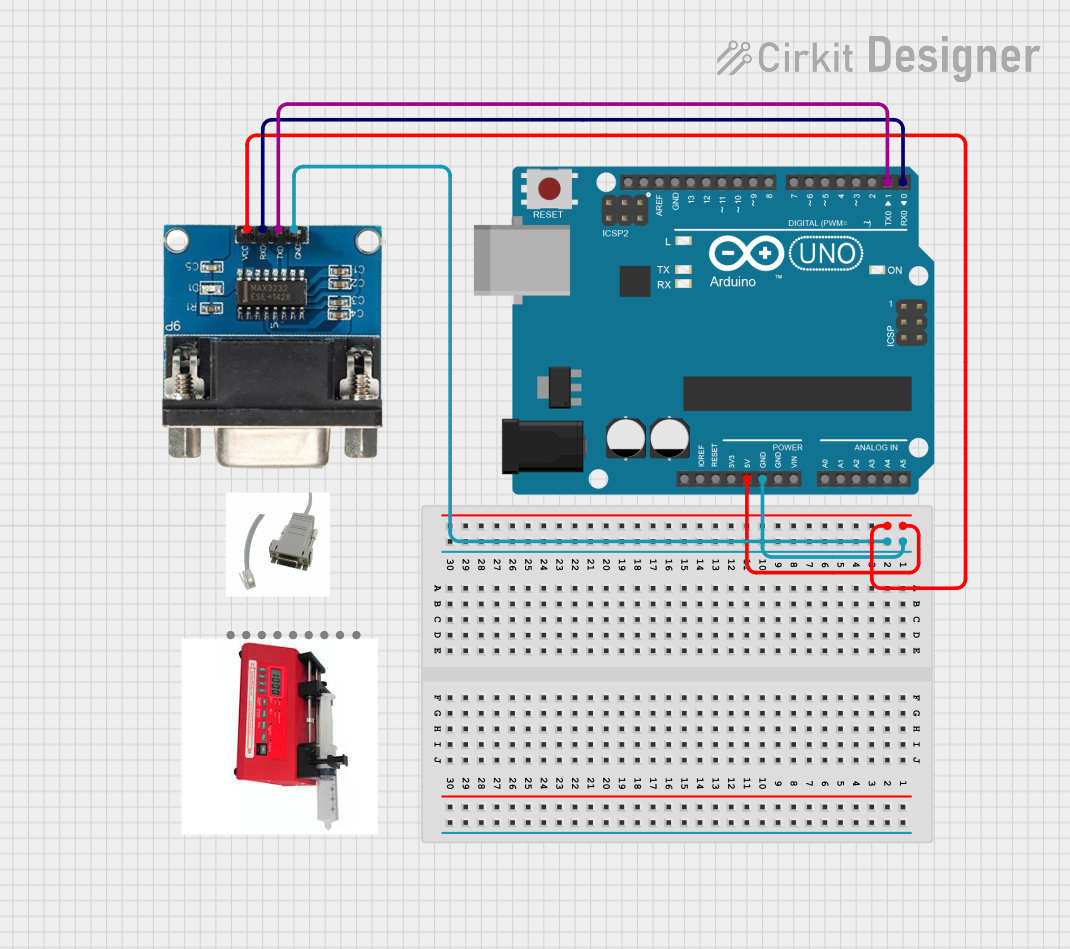
Example: Connecting RS232 Module to Arduino UNO

Below is an example of how to use the RS232 module with an Arduino UNO to send and receive data:

Circuit Connections

  • RS232 Module TXD → Arduino UNO RX (Pin 0)
  • RS232 Module RXD → Arduino UNO TX (Pin 1)
  • RS232 Module VCC → Arduino UNO 5V
  • RS232 Module GND → Arduino UNO GND

Arduino Code

// Example code to send and receive data using RS232 module with Arduino UNO

void setup() {
  Serial.begin(9600); // Initialize serial communication at 9600 baud
  Serial.println("RS232 Module Test"); // Send a test message
}

void loop() {
  // Check if data is available from the RS232 device
  if (Serial.available() > 0) {
    char receivedChar = Serial.read(); // Read the incoming character
    Serial.print("Received: "); // Print the received character
    Serial.println(receivedChar);
  }

  // Send a message to the RS232 device every 2 seconds
  delay(2000);
  Serial.println("Hello from Arduino!");
}

Troubleshooting and FAQs

Common Issues and Solutions

  1. No Data Transmission or Reception:

    • Verify the TX and RX connections between the RS232 module and the microcontroller.
    • Ensure the baud rate and serial settings match between the devices.
  2. Garbage Data Received:

    • Check for mismatched baud rates or incorrect parity/stop bit settings.
    • Ensure proper grounding between the RS232 module and the connected devices.
  3. RS232 Device Not Responding:

    • Confirm that the RS232 device is powered on and functioning.
    • If using hardware flow control, ensure RTS and CTS are correctly connected.
  4. Signal Interference:

    • Use shorter cables or shielded RS232 cables in noisy environments.
    • Avoid running RS232 cables near high-power lines or noisy equipment.

FAQs

Q: Can I use the RS232 module with a 3.3V microcontroller?
A: Yes, but ensure the module supports 3.3V logic levels. Some modules are designed for 5V only.

Q: What is the maximum cable length for RS232 communication?
A: The RS232 standard supports cable lengths up to 15 meters (50 feet) at lower baud rates. For higher baud rates, shorter cables are recommended.

Q: Do I need to use RTS and CTS pins?
A: RTS and CTS are optional and used for hardware flow control. If your device does not require flow control, you can leave these pins unconnected.

Q: Can I connect the RS232 module directly to a USB port?
A: No, RS232 and USB use different communication protocols. Use a USB-to-RS232 adapter if needed.