
How to Use HEX_CONVERTER: Examples, Pinouts, and Specs
 Design with HEX_CONVERTER in Cirkit Designer
Introduction
The HEX_CONVERTER is an electronic component designed to convert binary numbers into hexadecimal format and vice versa. This functionality is essential in digital systems where hexadecimal representation simplifies the manipulation and visualization of binary data. HEX_CONVERTERs are commonly used in microcontroller-based systems, digital displays, debugging tools, and data communication protocols.
Explore Projects Built with HEX_CONVERTER
 Open Project in Cirkit Designer
 Open Project in Cirkit Designer
 Open Project in Cirkit DesignerOpen Project in Cirkit Designer
Explore Projects Built with HEX_CONVERTER
Open Project in Cirkit DesignerOpen Project in Cirkit DesignerOpen Project in Cirkit DesignerOpen Project in Cirkit DesignerCommon Applications and Use Cases
- Microcontroller Programming: Simplifies binary data representation for debugging and programming.
- Digital Displays: Converts binary data to hexadecimal for easier visualization on 7-segment or alphanumeric displays.
- Data Communication: Facilitates data encoding and decoding in hexadecimal format for efficient transmission.
- Educational Tools: Used in teaching digital logic and number system conversions.
Technical Specifications
Key Technical Details
- Operating Voltage: 3.3V to 5V DC
- Current Consumption: 10mA (typical)
- Conversion Speed: Up to 1 MHz
- Input Format: 4-bit binary (for binary-to-hex conversion)
- Output Format: 4-bit binary or hexadecimal character (depending on mode)
- Operating Temperature: -40°C to 85°C
- Package Type: DIP-16 or SMD
Pin Configuration and Descriptions
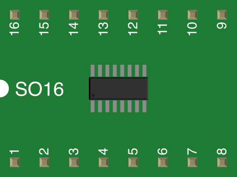
The HEX_CONVERTER typically comes in a 16-pin package. Below is the pinout description:
| Pin Number | Pin Name | Description |
|---|---|---|
| 1 | VCC | Power supply input (3.3V to 5V DC). |
| 2 | GND | Ground connection. |
| 3-6 | BIN_IN[3:0] | 4-bit binary input for binary-to-hex conversion. |
| 7 | HEX_OUT_EN | Enable pin for hexadecimal output. Active HIGH. |
| 8-11 | HEX_OUT[3:0] | 4-bit hexadecimal output. |
| 12 | MODE | Mode selection: HIGH for binary-to-hex, LOW for hex-to-binary. |
| 13-16 | HEX_IN[3:0] | 4-bit hexadecimal input for hex-to-binary conversion. |
Usage Instructions
How to Use the HEX_CONVERTER in a Circuit
- Power the Component: Connect the VCC pin to a 3.3V or 5V DC power supply and the GND pin to ground.
- Select the Mode: Use the MODE pin to choose the desired operation:
- Set MODE to HIGH for binary-to-hexadecimal conversion.
- Set MODE to LOW for hexadecimal-to-binary conversion.
- Provide Input Data:
- For binary-to-hex conversion, input a 4-bit binary number to the BIN_IN[3:0] pins.
- For hex-to-binary conversion, input a 4-bit hexadecimal number to the HEX_IN[3:0] pins.
- Enable Output: Set the HEX_OUT_EN pin to HIGH to activate the output pins.
- Read the Output:
- For binary-to-hex conversion, read the 4-bit hexadecimal output from HEX_OUT[3:0].
- For hex-to-binary conversion, read the 4-bit binary output from BIN_IN[3:0].
Important Considerations and Best Practices
- Ensure the power supply voltage matches the component's operating range (3.3V to 5V).
- Use pull-down resistors on unused input pins to prevent floating states.
- Avoid exceeding the maximum input frequency of 1 MHz to ensure accurate conversions.
- When interfacing with microcontrollers, use level shifters if voltage levels differ.
Example: Using HEX_CONVERTER with Arduino UNO
Below is an example of interfacing the HEX_CONVERTER with an Arduino UNO for binary-to-hexadecimal conversion:
// Define input and output pins for the HEX_CONVERTER
const int binInputPins[4] = {2, 3, 4, 5}; // Binary input pins
const int hexOutputPins[4] = {6, 7, 8, 9}; // Hexadecimal output pins
const int modePin = 10; // Mode selection pin
const int enablePin = 11; // Output enable pin

void setup() {
  // Set binary input pins as outputs
  for (int i = 0; i < 4; i++) {
    pinMode(binInputPins[i], OUTPUT);
  }

  // Set hexadecimal output pins as inputs
  for (int i = 0; i < 4; i++) {
    pinMode(hexOutputPins[i], INPUT);
  }

  // Set mode and enable pins as outputs
  pinMode(modePin, OUTPUT);
  pinMode(enablePin, OUTPUT);

  // Configure the HEX_CONVERTER for binary-to-hex conversion
  digitalWrite(modePin, HIGH); // Set mode to binary-to-hex
  digitalWrite(enablePin, HIGH); // Enable output
}

void loop() {
  // Example binary input: 1010 (decimal 10)
  int binaryInput[4] = {1, 0, 1, 0};

  // Write binary input to the HEX_CONVERTER
  for (int i = 0; i < 4; i++) {
    digitalWrite(binInputPins[i], binaryInput[i]);
  }

  // Read hexadecimal output from the HEX_CONVERTER
  int hexOutput[4];
  for (int i = 0; i < 4; i++) {
    hexOutput[i] = digitalRead(hexOutputPins[i]);
  }

  // Print the hexadecimal output to the Serial Monitor
  Serial.begin(9600);
  Serial.print("Hexadecimal Output: ");
  for (int i = 0; i < 4; i++) {
    Serial.print(hexOutput[i]);
  }
  Serial.println();

  delay(1000); // Wait for 1 second before repeating
}
Troubleshooting and FAQs
Common Issues and Solutions
No Output on HEX_OUT Pins:
- Ensure the HEX_OUT_EN pin is set to HIGH.
- Verify the power supply voltage is within the operating range.
- Check for loose or incorrect connections.
Incorrect Conversion Results:
- Confirm the input data format matches the selected mode (binary or hexadecimal).
- Ensure the input frequency does not exceed 1 MHz.
Floating or Unstable Outputs:
- Use pull-down resistors on unused input pins.
- Check for noise or interference in the circuit.
FAQs
Q1: Can the HEX_CONVERTER handle more than 4 bits of input?
A1: No, the HEX_CONVERTER is designed for 4-bit binary and hexadecimal conversions. For larger data sizes, use multiple HEX_CONVERTERs or a microcontroller.
Q2: Is the HEX_CONVERTER compatible with 3.3V systems?
A2: Yes, the HEX_CONVERTER operates within a voltage range of 3.3V to 5V.
Q3: Can I use the HEX_CONVERTER for real-time data conversion?
A3: Yes, the HEX_CONVERTER supports conversion speeds up to 1 MHz, making it suitable for real-time applications.