How to Use Gravity Analog Isolation Module V1.0: Examples, Pinouts, and Specs
Introduction
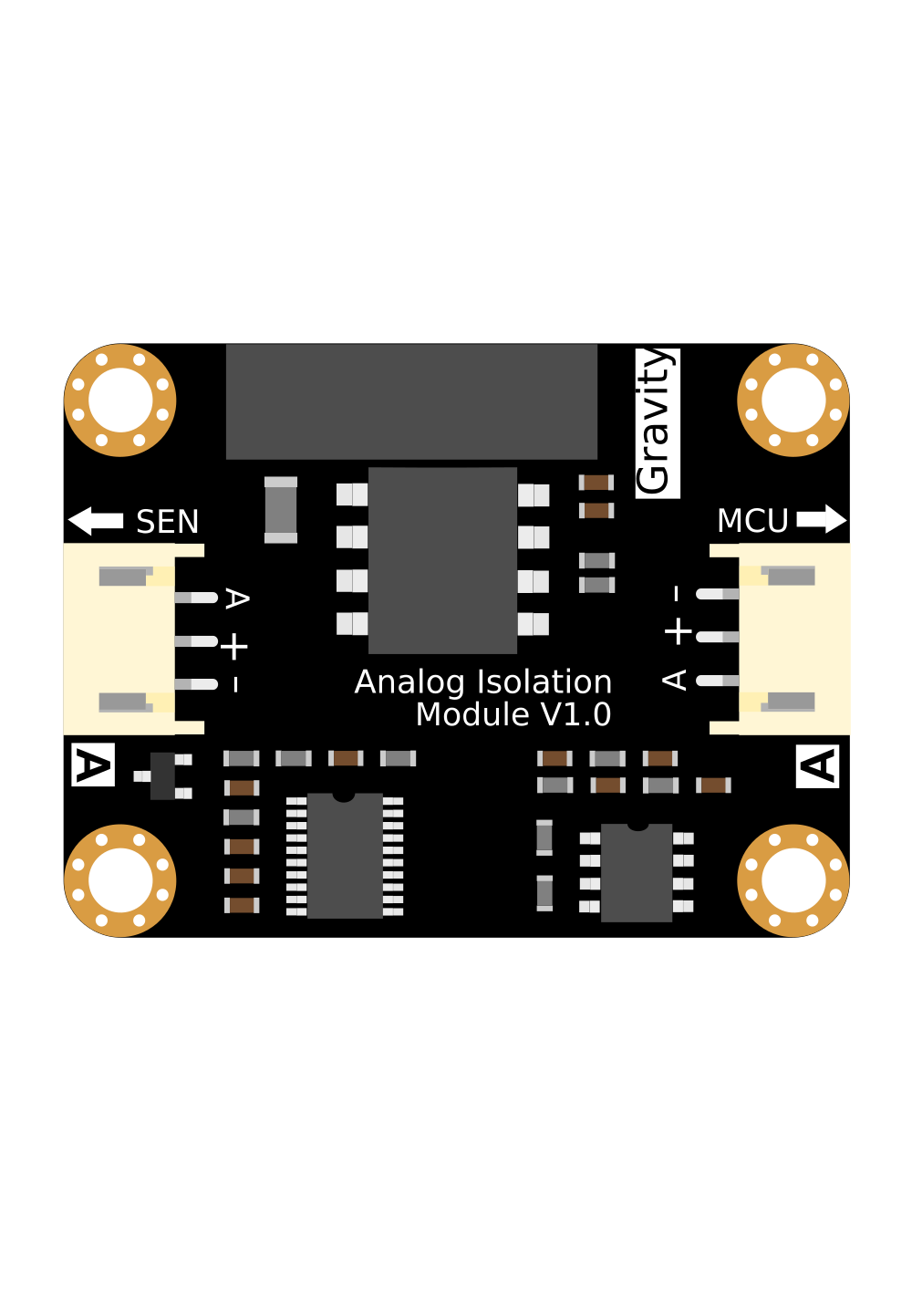
The Gravity Analog Isolation Module V1.0 (Manufacturer Part ID: DFR0504) by DFROBOT is a specialized module designed to isolate analog signals from noise and interference. It ensures accurate signal transmission, making it ideal for applications where signal integrity is critical. This module is particularly useful in scenarios involving long-distance signal transmission, industrial environments, or when interfacing sensitive analog sensors with microcontrollers.
Explore Projects Built with Gravity Analog Isolation Module V1.0


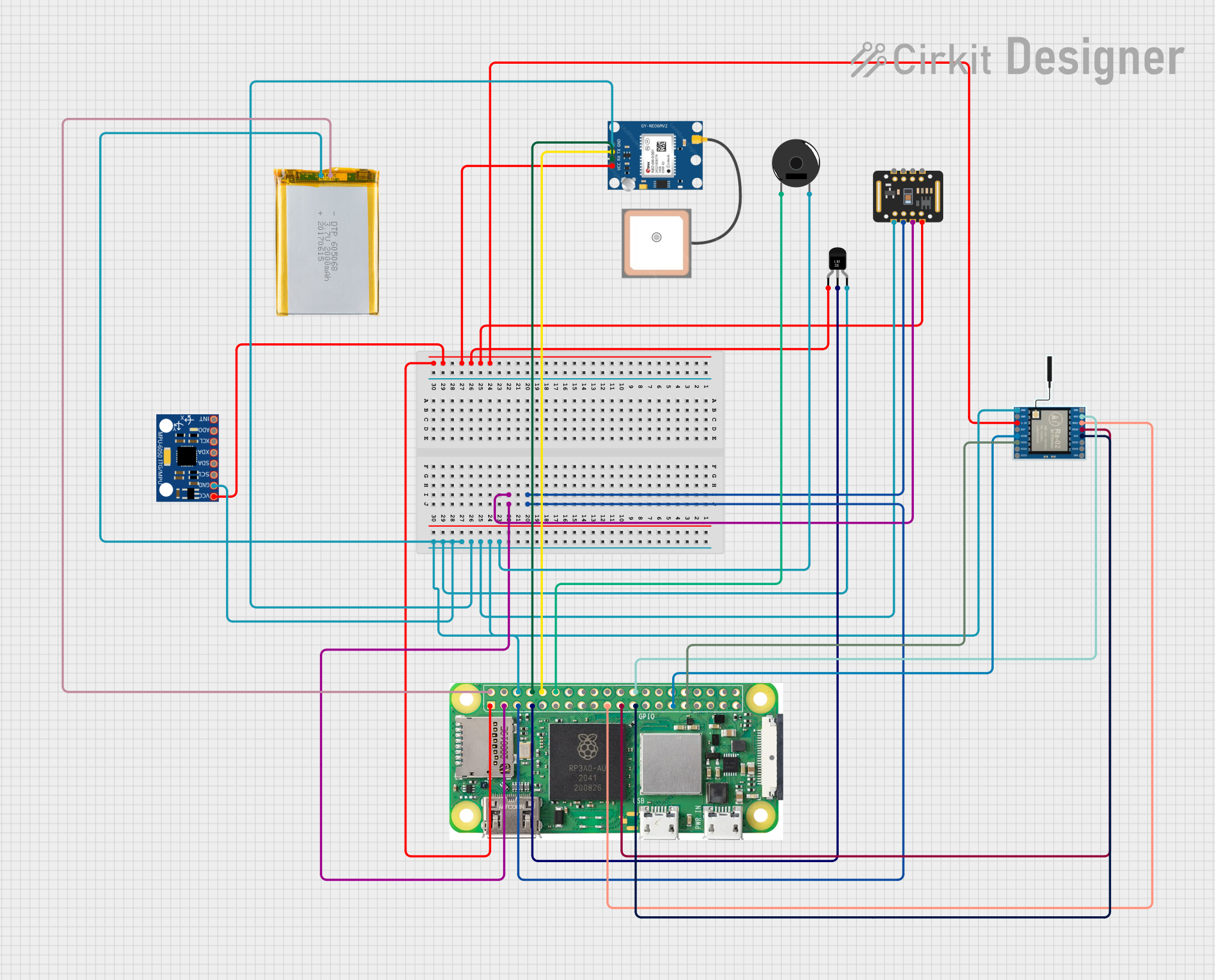
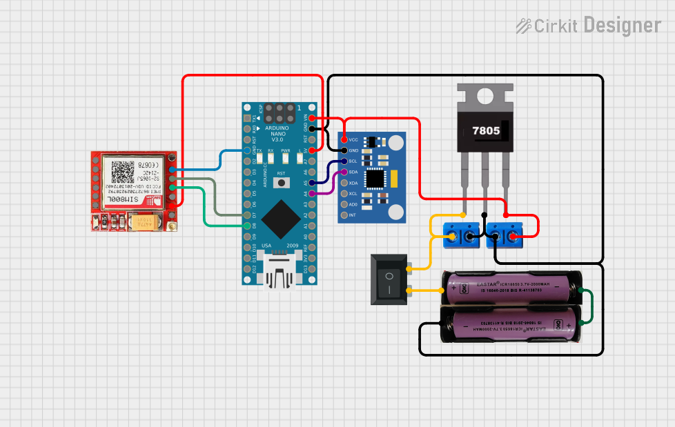
Explore Projects Built with Gravity Analog Isolation Module V1.0
Common Applications and Use Cases
- Signal isolation in noisy environments
- Long-distance analog signal transmission
- Industrial automation and control systems
- Interfacing sensitive analog sensors with microcontrollers
- Medical instrumentation and precision measurement systems
Technical Specifications
The following table outlines the key technical details of the Gravity Analog Isolation Module V1.0:
| Parameter | Specification |
|---|---|
| Operating Voltage | 3.3V to 5.5V |
| Signal Input Range | 0-3.3V (default) |
| Signal Output Range | 0-3.3V (default) |
| Isolation Voltage | 2500V DC |
| Operating Temperature | -40°C to 85°C |
| Dimensions | 30mm x 22mm |
| Weight | 5g |
Pin Configuration and Descriptions
The module features a simple pinout for easy integration into your projects. The pin configuration is as follows:
| Pin | Name | Description |
|---|---|---|
| 1 | VCC | Power supply input (3.3V to 5.5V) |
| 2 | GND | Ground connection |
| 3 | Signal Input | Analog signal input (0-3.3V by default, adjustable via onboard potentiometer) |
| 4 | Signal Output | Isolated analog signal output (0-3.3V by default) |
Usage Instructions
How to Use the Component in a Circuit
- Power the Module: Connect the
VCCpin to a 3.3V or 5V power source and theGNDpin to the ground of your circuit. - Connect the Input Signal: Attach the analog signal source (e.g., a sensor) to the
Signal Inputpin. - Retrieve the Isolated Signal: Connect the
Signal Outputpin to the analog input of your microcontroller or other receiving device. - Adjust the Signal Range (Optional): Use the onboard potentiometer to fine-tune the input/output signal range if needed.
Important Considerations and Best Practices
- Power Supply: Ensure a stable power supply to avoid introducing noise into the module.
- Signal Range: The default signal range is 0-3.3V. If your application requires a different range, adjust the onboard potentiometer carefully.
- Isolation: The module provides up to 2500V DC isolation. Ensure that the input and output circuits are properly isolated to prevent damage.
- Mounting: Secure the module in your project to avoid mechanical stress on the pins or PCB.
Example: Connecting to an Arduino UNO
The Gravity Analog Isolation Module can be easily interfaced with an Arduino UNO. Below is an example of how to read an isolated analog signal:
Circuit Connections
- Connect the
VCCpin of the module to the 5V pin on the Arduino. - Connect the
GNDpin of the module to the GND pin on the Arduino. - Connect the
Signal Inputpin to your analog signal source (e.g., a potentiometer or sensor). - Connect the
Signal Outputpin to an analog input pin on the Arduino (e.g., A0).
Arduino Code
// Example code to read an isolated analog signal using the Gravity Analog Isolation Module
const int analogPin = A0; // Pin connected to the Signal Output of the module

void setup() {
  Serial.begin(9600); // Initialize serial communication at 9600 baud
}

void loop() {
  int analogValue = analogRead(analogPin); // Read the analog value from the module
  float voltage = analogValue * (5.0 / 1023.0); // Convert the reading to voltage
  Serial.print("Analog Value: ");
  Serial.print(analogValue);
  Serial.print(" | Voltage: ");
  Serial.print(voltage);
  Serial.println(" V");
  delay(500); // Wait for 500ms before the next reading
}
Troubleshooting and FAQs
Common Issues and Solutions
No Output Signal
- Cause: Incorrect wiring or no input signal.
- Solution: Double-check the connections and ensure the input signal is within the specified range.
Distorted Output Signal
- Cause: Noise in the power supply or incorrect signal range adjustment.
- Solution: Use a stable power source and adjust the onboard potentiometer carefully.
Output Signal Not Isolated
- Cause: Improper grounding or short circuit between input and output.
- Solution: Ensure proper isolation between the input and output circuits.
Module Overheating
- Cause: Exceeding the operating voltage or current limits.
- Solution: Verify that the power supply voltage is within the 3.3V to 5.5V range.
FAQs
Q1: Can the module handle signals above 3.3V?
A1: No, the default signal range is 0-3.3V. However, you can adjust the range using the onboard potentiometer. Ensure the input signal does not exceed the module's maximum voltage rating.
Q2: Can I use this module with a 3.3V microcontroller?
A2: Yes, the module is compatible with both 3.3V and 5V systems.
Q3: How do I know if the module is working correctly?
A3: Measure the output signal with a multimeter or oscilloscope and compare it to the input signal. The output should match the input within the specified range, but it will be electrically isolated.
Q4: Is the module suitable for AC signals?
A4: The module is primarily designed for DC analog signals. For AC signals, additional circuitry may be required to ensure proper operation.
By following this documentation, you can effectively integrate the Gravity Analog Isolation Module V1.0 into your projects and ensure reliable, noise-free signal transmission.