How to Use esp32 38p typec cp2102: Examples, Pinouts, and Specs
Introduction
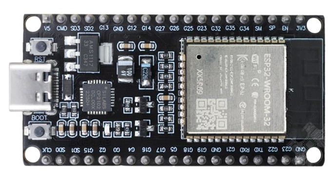
The ESP32 38P Type-C CP2102 is a versatile and powerful microcontroller module developed by Espressif Systems. It is based on the ESP32 dual-core processor, which integrates Wi-Fi and Bluetooth capabilities, making it ideal for IoT (Internet of Things) applications. This module features a USB Type-C interface for easy connectivity and a CP2102 USB-to-UART bridge for seamless communication with a computer.
Explore Projects Built with esp32 38p typec cp2102

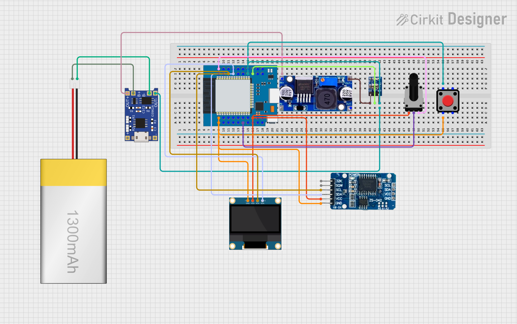
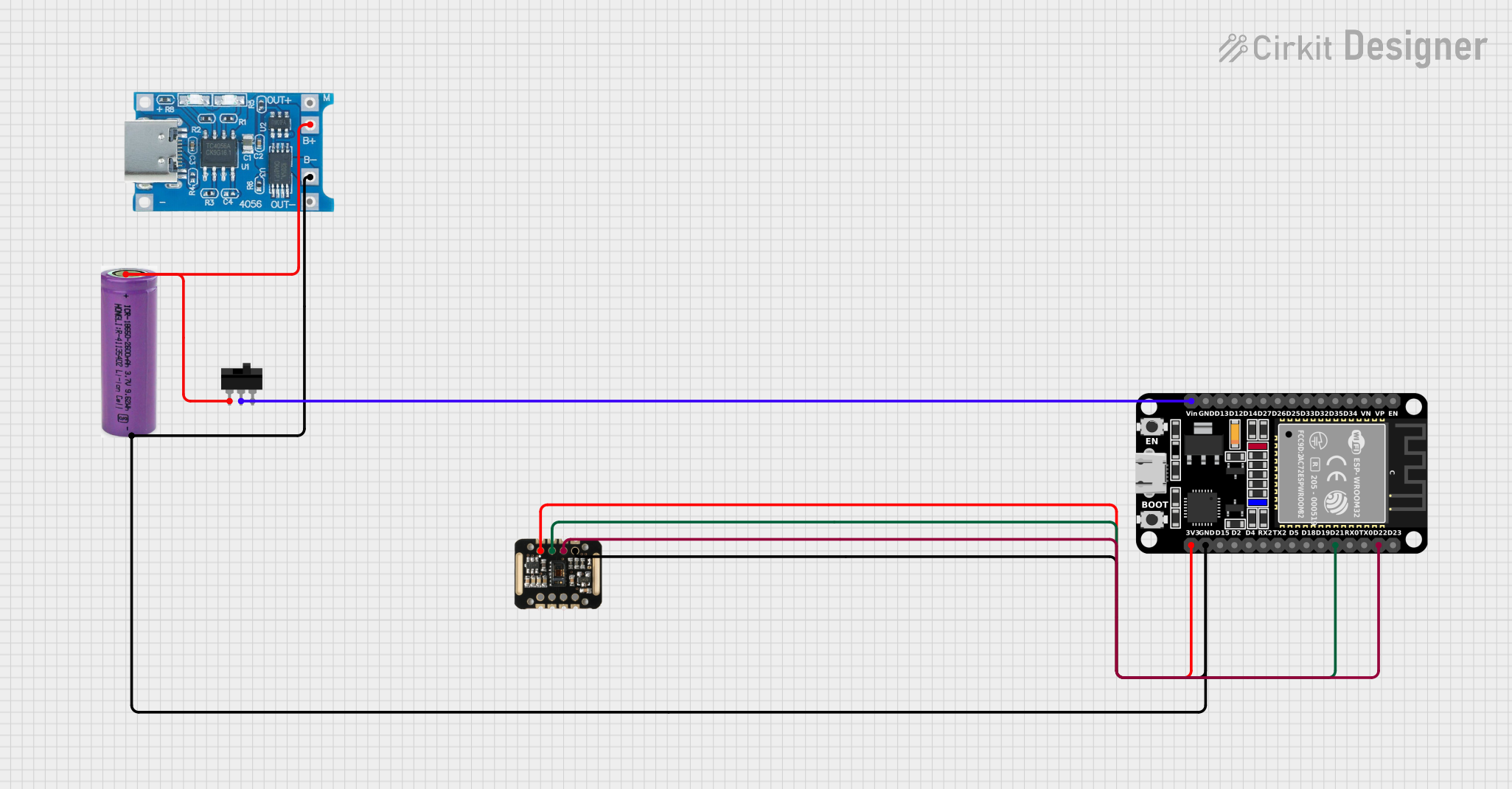

Explore Projects Built with esp32 38p typec cp2102
Common Applications and Use Cases
- IoT devices and smart home automation
- Wireless sensor networks
- Wearable electronics
- Robotics and drones
- Prototyping and development of Wi-Fi/Bluetooth-enabled devices
Technical Specifications
Key Technical Details
- Processor: Dual-core Xtensa® 32-bit LX6 CPU
- Clock Speed: Up to 240 MHz
- Flash Memory: 4 MB (varies by model)
- SRAM: 520 KB
- Wireless Connectivity: Wi-Fi 802.11 b/g/n and Bluetooth 4.2 (Classic + BLE)
- Operating Voltage: 3.3V
- Input Voltage: 5V (via USB Type-C)
- GPIO Pins: 38
- USB Interface: CP2102 USB-to-UART bridge
- Power Consumption: Ultra-low power consumption in deep sleep mode (~10 µA)
- Dimensions: 51mm x 25.5mm
Pin Configuration and Descriptions
The ESP32 38P module has 38 pins, each with specific functions. Below is a table summarizing the key pins:
| Pin Name | Function | Description |
|---|---|---|
| VIN | Power Input | Connect to 5V power source (via USB Type-C or external supply). |
| GND | Ground | Common ground for the module. |
| 3V3 | 3.3V Output | Provides 3.3V output for external components. |
| EN | Enable | Active-high pin to enable the module. |
| IO0 | GPIO0 / Boot Mode | Used for boot mode selection or general-purpose I/O. |
| IO2 | GPIO2 | General-purpose I/O pin. |
| IO4 | GPIO4 | General-purpose I/O pin. |
| IO5 | GPIO5 | General-purpose I/O pin. |
| IO12 | GPIO12 | General-purpose I/O pin. |
| IO13 | GPIO13 | General-purpose I/O pin. |
| IO14 | GPIO14 | General-purpose I/O pin. |
| IO15 | GPIO15 | General-purpose I/O pin. |
| IO16 | GPIO16 | General-purpose I/O pin. |
| IO17 | GPIO17 | General-purpose I/O pin. |
| IO18 | GPIO18 / SPI_CLK | General-purpose I/O or SPI clock pin. |
| IO19 | GPIO19 / SPI_MISO | General-purpose I/O or SPI MISO pin. |
| IO21 | GPIO21 / I2C_SDA | General-purpose I/O or I2C data pin. |
| IO22 | GPIO22 / I2C_SCL | General-purpose I/O or I2C clock pin. |
| IO23 | GPIO23 / SPI_MOSI | General-purpose I/O or SPI MOSI pin. |
| IO25 | GPIO25 / DAC1 | General-purpose I/O or DAC output. |
| IO26 | GPIO26 / DAC2 | General-purpose I/O or DAC output. |
| IO27 | GPIO27 | General-purpose I/O pin. |
| IO32 | GPIO32 / ADC1_CH4 | General-purpose I/O or ADC input channel 4. |
| IO33 | GPIO33 / ADC1_CH5 | General-purpose I/O or ADC input channel 5. |
| IO34 | GPIO34 / ADC1_CH6 (Input Only) | ADC input channel 6 (input-only pin). |
| IO35 | GPIO35 / ADC1_CH7 (Input Only) | ADC input channel 7 (input-only pin). |
Usage Instructions
How to Use the ESP32 38P in a Circuit
Powering the Module:
- Connect the module to a 5V power source using the USB Type-C port or the VIN pin.
- Ensure the GND pin is connected to the ground of your circuit.
Programming the Module:
- Install the CP2102 USB-to-UART driver on your computer (if not already installed).
- Use the Arduino IDE or Espressif's ESP-IDF to write and upload code to the module.
- Select the correct board (e.g., "ESP32 Dev Module") and COM port in the Arduino IDE.
Connecting Peripherals:
- Use the GPIO pins to connect sensors, actuators, or other peripherals.
- For I2C devices, use GPIO21 (SDA) and GPIO22 (SCL).
- For SPI devices, use GPIO18 (CLK), GPIO19 (MISO), and GPIO23 (MOSI).
Boot Mode Selection:
- To enter bootloader mode, hold the IO0 pin low while resetting the module.
Important Considerations and Best Practices
- Voltage Levels: Ensure all connected peripherals operate at 3.3V logic levels to avoid damaging the module.
- Deep Sleep Mode: Use deep sleep mode to minimize power consumption in battery-powered applications.
- Antenna Placement: Avoid placing metal objects near the onboard antenna to ensure optimal Wi-Fi and Bluetooth performance.
- Heat Management: The ESP32 can get warm during operation; ensure proper ventilation if used in enclosed spaces.
Example Code for Arduino UNO Integration
Below is an example of using the ESP32 38P to blink an LED connected to GPIO2:
// Example: Blink an LED connected to GPIO2 on the ESP32 38P module

// Define the GPIO pin for the LED
#define LED_PIN 2

void setup() {
  // Initialize the LED pin as an output
  pinMode(LED_PIN, OUTPUT);
}

void loop() {
  // Turn the LED on
  digitalWrite(LED_PIN, HIGH);
  delay(1000); // Wait for 1 second

  // Turn the LED off
  digitalWrite(LED_PIN, LOW);
  delay(1000); // Wait for 1 second
}
Troubleshooting and FAQs
Common Issues and Solutions
Issue: The ESP32 is not detected by the computer.
Solution:- Ensure the CP2102 driver is installed correctly.
- Check the USB cable for data transfer capability (some cables are power-only).
- Try a different USB port or cable.
Issue: Unable to upload code to the ESP32.
Solution:- Ensure the correct board and COM port are selected in the Arduino IDE.
- Hold the IO0 pin low while pressing the reset button to enter bootloader mode.
Issue: Wi-Fi or Bluetooth connectivity issues.
Solution:- Check the antenna placement and ensure no obstructions.
- Verify the Wi-Fi credentials or Bluetooth pairing process.
Issue: Module overheating during operation.
Solution:- Reduce the clock speed or optimize the code to minimize CPU usage.
- Ensure proper ventilation or add a heatsink if necessary.
FAQs
Q: Can the ESP32 38P be powered by a battery?
A: Yes, you can power the module using a 3.7V LiPo battery connected to the VIN pin with a suitable voltage regulator.Q: What is the maximum number of GPIO pins available?
A: The module provides 38 GPIO pins, but some are shared with other functions (e.g., ADC, DAC, SPI).Q: Does the module support OTA (Over-the-Air) updates?
A: Yes, the ESP32 supports OTA updates, which can be implemented using the Arduino IDE or ESP-IDF.Q: Can I use the ESP32 38P with MicroPython?
A: Yes, the ESP32 is compatible with MicroPython. You can flash the MicroPython firmware to the module and use it for development.