How to Use 2.2 inch Basic Flex Resistor: Examples, Pinouts, and Specs

Introduction
The 2.2 inch Basic Flex Resistor is a flexible, variable resistor that adjusts its resistance in response to bending or flexing. This component is ideal for applications requiring input based on physical manipulation, such as in wearable electronics, robotics, or interactive installations. Common use cases include volume control, soft potentiometers, and pressure sensing.
Explore Projects Built with 2.2 inch Basic Flex Resistor
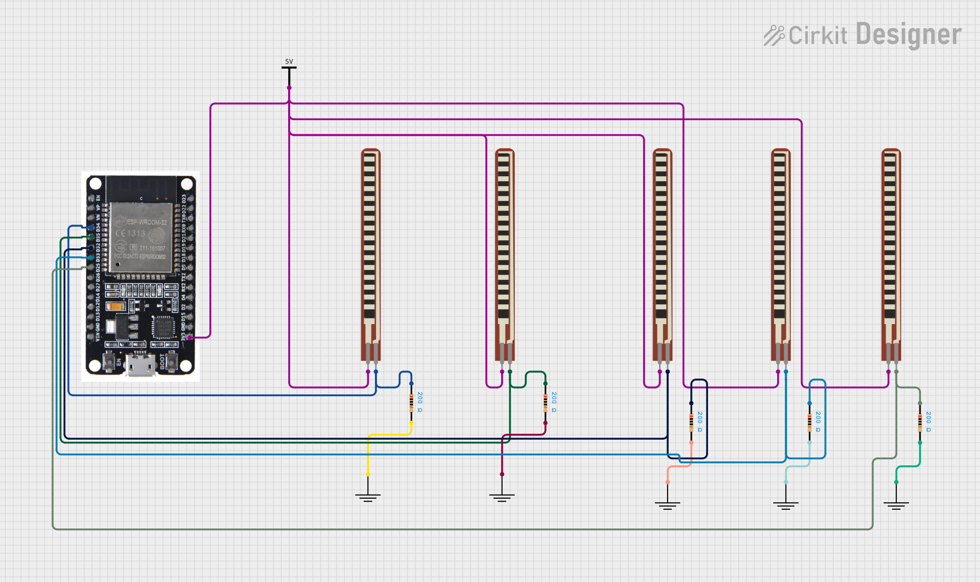
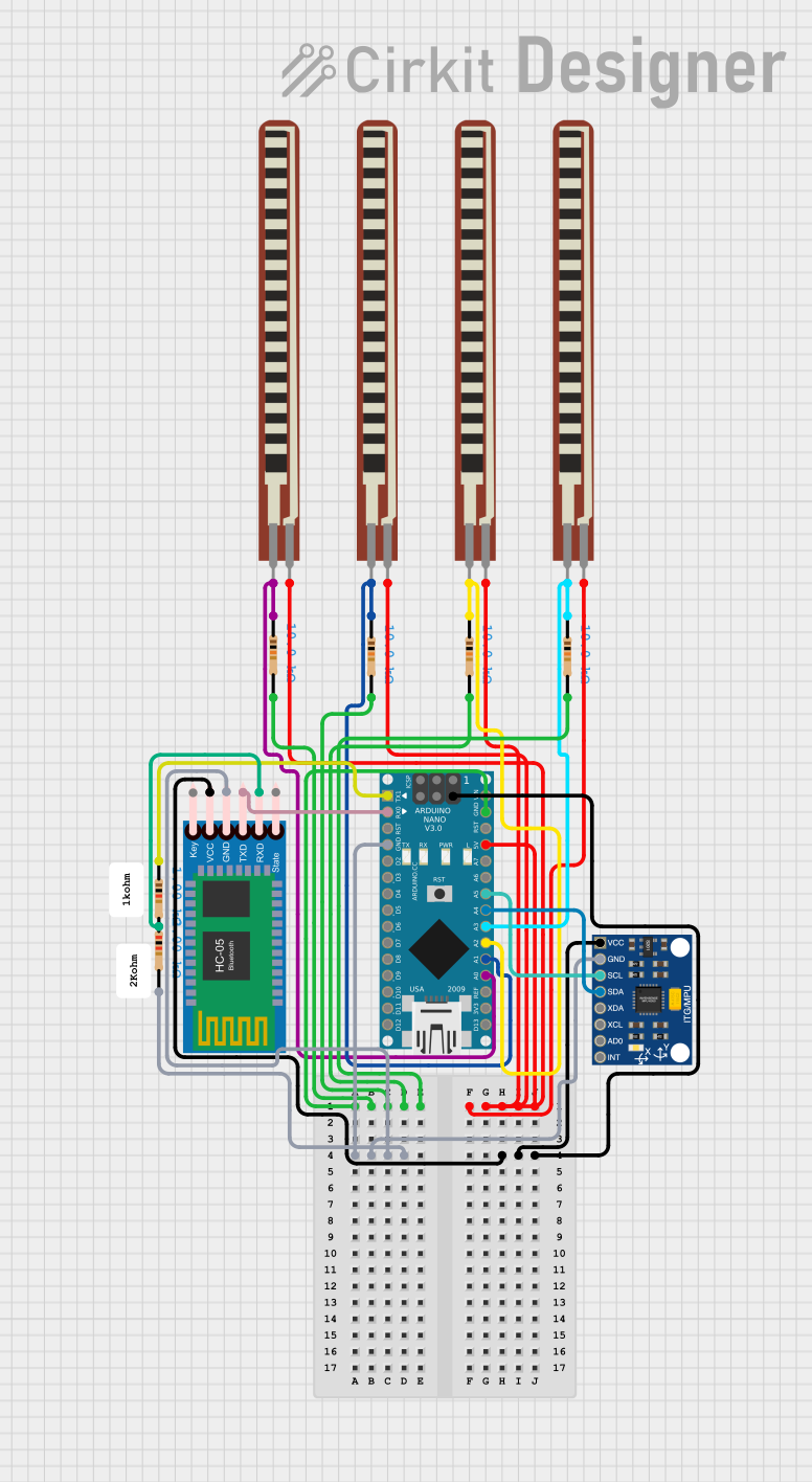
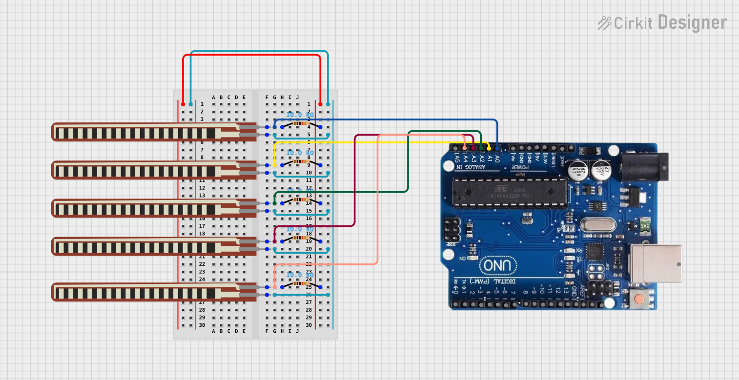
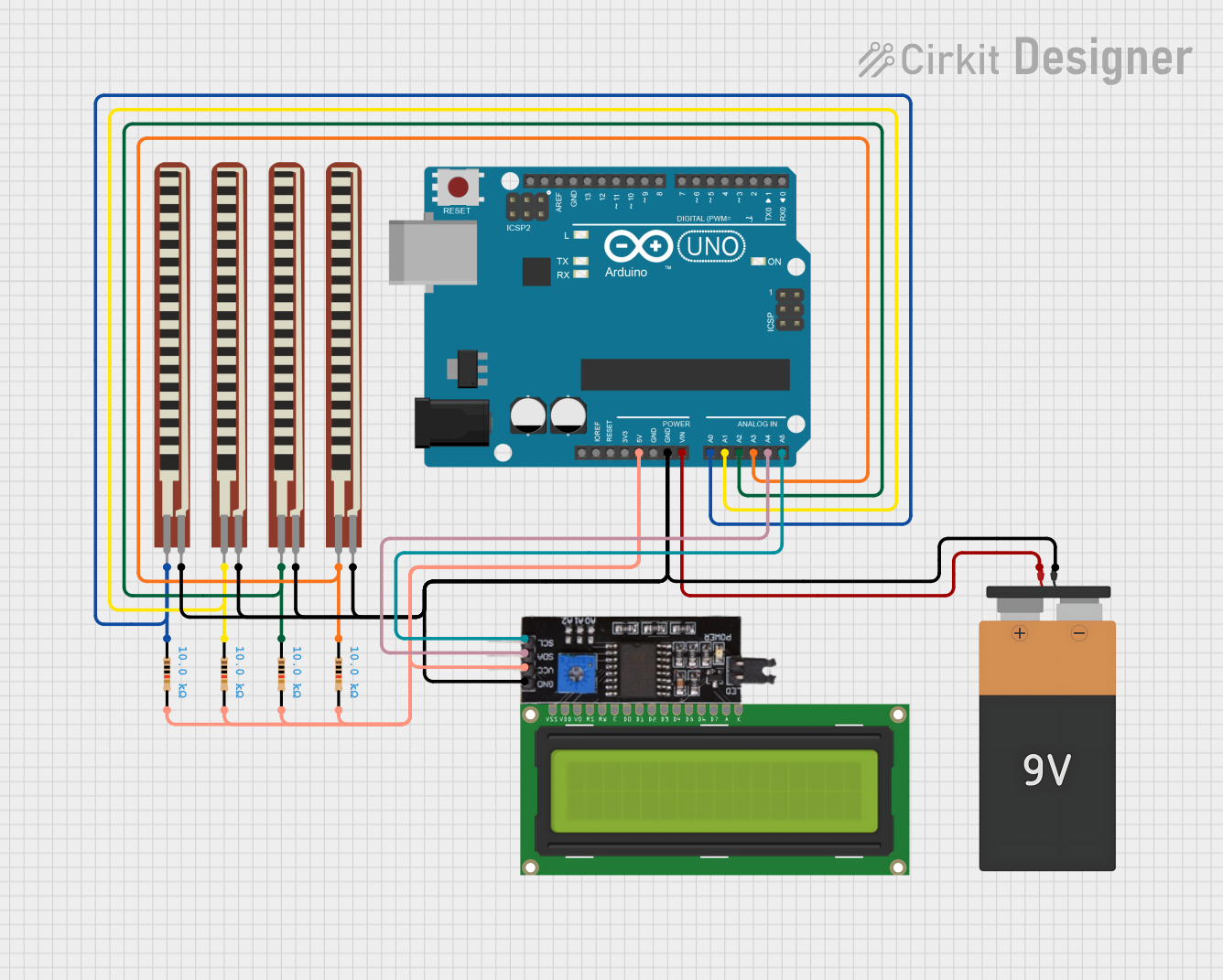
Explore Projects Built with 2.2 inch Basic Flex Resistor
Technical Specifications
Key Technical Details
- Resistance Range: Typically 10kΩ to 30kΩ when flat, increasing when bent
- Tolerance: ±30%
- Power Rating: 0.5 Watts (maximum)
- Operating Temperature: -30°C to +70°C
- Dimensions: 2.2 inches in length
- Bend Radius: Minimum 2mm for flexing without damage
Pin Configuration and Descriptions
| Pin Number | Description |
|---|---|
| 1 | Resistance End 1 |
| 2 | Resistance End 2 |
Usage Instructions
Integration into a Circuit
To use the 2.2 inch Basic Flex Resistor in a circuit, connect each end to a different point in the circuit where variable resistance is needed. It can be used in a voltage divider configuration to provide an analog input to microcontrollers like the Arduino UNO.
Best Practices
- Avoid sharp bends that may damage the resistor.
- Secure the resistor to a stable surface to prevent unwanted flexing.
- Use strain relief at the connection points to prevent detachment or wear.
- Calibrate the sensor in your application, as the resistance range can vary.
Example Code for Arduino UNO
// Define the pin connected to the flex resistor
const int flexPin = A0;

void setup() {
  // Begin serial communication at 9600 baud rate
  Serial.begin(9600);
}

void loop() {
  // Read the analog value from the flex resistor
  int flexValue = analogRead(flexPin);

  // Map the analog value to the range of the flex resistor
  int resistance = map(flexValue, 0, 1023, 10000, 30000);

  // Print the resistance value to the Serial Monitor
  Serial.println("Resistance: " + String(resistance) + " ohms");

  // Delay for a bit to avoid spamming the Serial Monitor
  delay(500);
}
Note: The map function in the code is a simple way to convert the analog reading (0-1023) to an estimated resistance range (10kΩ to 30kΩ). For more accurate results, a calibration process is recommended.
Troubleshooting and FAQs
Common Issues
- Inconsistent Readings: Ensure the flex resistor is not experiencing intermittent connections or is partially detached from the circuit.
- Resistance Not Changing: Verify that the resistor is actually flexing and that the connections are secure.
- Damage to the Resistor: If the resistor has been bent sharply or flexed beyond its limits, it may be damaged. Inspect for physical signs of damage.
FAQs
Q: Can I trim the flex resistor to a shorter length? A: No, trimming the flex resistor will damage it and alter its resistance properties.
Q: How do I calibrate the flex resistor for precise measurements? A: Use a multimeter to measure the resistance at known bend angles and create a calibration curve or table for your specific application.
Q: Is the flex resistor waterproof? A: No, the flex resistor is not waterproof and should be protected from moisture to prevent damage.
For further assistance, please refer to the manufacturer's datasheet or contact technical support.