Cirkit Designer Logo
Cirkit Designer
Your all-in-one circuit design IDE
Home / 
Component Documentation

How to Use RDA5807M: Examples, Pinouts, and Specs

Image of RDA5807M
Cirkit Designer LogoDesign with RDA5807M in Cirkit Designer

Introduction

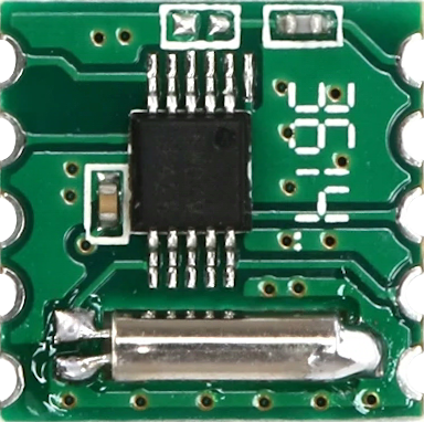
The RDA5807M is a single-chip broadcast FM radio tuner developed by RDA Microelectronics. It features a fully integrated synthesizer, IF selectivity, and MPX decoder. This component supports worldwide FM band reception and is designed for low power consumption, making it ideal for portable devices such as MP3 players, smartphones, and portable radios.

Explore Projects Built with RDA5807M

Use Cirkit Designer to design, explore, and prototype these projects online. Some projects support real-time simulation. Click "Open Project" to start designing instantly!
Arduino Pro Mini FM Radio with LCD Display and Battery Power
Image of DIY FM Radio RDA5807M V2: A project utilizing RDA5807M in a practical application
This circuit is a portable FM radio receiver with an integrated display and audio output. It uses an Arduino Pro Mini to control an RDA5807M FM receiver module, an ADS1115 ADC for additional analog inputs, and a PAM8403 amplifier to drive loudspeakers. The circuit also includes a rotary encoder for user input, an LCD screen for displaying information, and a boost converter for power management.
Cirkit Designer LogoOpen Project in Cirkit Designer
ESP32-Powered Wi-Fi Controlled Robotic Car with OLED Display and Ultrasonic Sensor
Image of playbot: A project utilizing RDA5807M in a practical application
This circuit is a battery-powered system featuring an ESP32 microcontroller that controls an OLED display, a motor driver for two hobby motors, an ultrasonic sensor for distance measurement, and a DFPlayer Mini for audio output through a loudspeaker. The TP4056 module manages battery charging, and a step-up boost converter provides a stable 5V supply to the components.
Cirkit Designer LogoOpen Project in Cirkit Designer
Arduino Mega ADK Automated Plant Watering and Environmental Monitoring System
Image of Automatisierungsprojekt Mega: A project utilizing RDA5807M in a practical application
This circuit features an Arduino Mega ADK as the central microcontroller, interfacing with a variety of sensors and actuators. It includes a BH1750 light sensor and a DHT11 temperature and humidity sensor for environmental monitoring, both interfacing via I2C. The system controls a stepper motor via an A4988 driver, two water pumps through a 3-channel relay, and a fan using an IRF520 PWM module, with several push switches to trigger inputs. An OLED display provides a user interface, and soil moisture levels are monitored with two soil sensors. A non-contact water level sensor is also included for liquid level detection.
Cirkit Designer LogoOpen Project in Cirkit Designer
Arduino Nano-Based Smart Relay Controller with RS485 Communication
Image of RELAY RS485: A project utilizing RDA5807M in a practical application
This circuit features an Arduino Nano controlling an 8-channel relay module, with each relay channel connected to digital pins D2 through D9. Additionally, the Arduino interfaces with an RS485 module for serial communication, which is connected to an RS485 to USB converter. Power is supplied through an LM2596 step-down module.
Cirkit Designer LogoOpen Project in Cirkit Designer

Explore Projects Built with RDA5807M

Use Cirkit Designer to design, explore, and prototype these projects online. Some projects support real-time simulation. Click "Open Project" to start designing instantly!
Image of DIY FM Radio RDA5807M V2: A project utilizing RDA5807M in a practical application
Arduino Pro Mini FM Radio with LCD Display and Battery Power
This circuit is a portable FM radio receiver with an integrated display and audio output. It uses an Arduino Pro Mini to control an RDA5807M FM receiver module, an ADS1115 ADC for additional analog inputs, and a PAM8403 amplifier to drive loudspeakers. The circuit also includes a rotary encoder for user input, an LCD screen for displaying information, and a boost converter for power management.
Cirkit Designer LogoOpen Project in Cirkit Designer
Image of playbot: A project utilizing RDA5807M in a practical application
ESP32-Powered Wi-Fi Controlled Robotic Car with OLED Display and Ultrasonic Sensor
This circuit is a battery-powered system featuring an ESP32 microcontroller that controls an OLED display, a motor driver for two hobby motors, an ultrasonic sensor for distance measurement, and a DFPlayer Mini for audio output through a loudspeaker. The TP4056 module manages battery charging, and a step-up boost converter provides a stable 5V supply to the components.
Cirkit Designer LogoOpen Project in Cirkit Designer
Image of Automatisierungsprojekt Mega: A project utilizing RDA5807M in a practical application
Arduino Mega ADK Automated Plant Watering and Environmental Monitoring System
This circuit features an Arduino Mega ADK as the central microcontroller, interfacing with a variety of sensors and actuators. It includes a BH1750 light sensor and a DHT11 temperature and humidity sensor for environmental monitoring, both interfacing via I2C. The system controls a stepper motor via an A4988 driver, two water pumps through a 3-channel relay, and a fan using an IRF520 PWM module, with several push switches to trigger inputs. An OLED display provides a user interface, and soil moisture levels are monitored with two soil sensors. A non-contact water level sensor is also included for liquid level detection.
Cirkit Designer LogoOpen Project in Cirkit Designer
Image of RELAY RS485: A project utilizing RDA5807M in a practical application
Arduino Nano-Based Smart Relay Controller with RS485 Communication
This circuit features an Arduino Nano controlling an 8-channel relay module, with each relay channel connected to digital pins D2 through D9. Additionally, the Arduino interfaces with an RS485 module for serial communication, which is connected to an RS485 to USB converter. Power is supplied through an LM2596 step-down module.
Cirkit Designer LogoOpen Project in Cirkit Designer

Technical Specifications

Key Technical Details

Parameter Value
Supply Voltage 2.7V to 3.6V
Operating Current 15mA (typical)
Frequency Range 50MHz to 115MHz
Channel Spacing 100kHz, 200kHz
Sensitivity -107dBm
Signal-to-Noise Ratio 60dB
Audio Output Stereo/Mono
Package SOP16, SSOP16

Pin Configuration and Descriptions

Pin No. Pin Name Description
1 LOUT Left audio output
2 ROUT Right audio output
3 GND Ground
4 VDD Power supply
5 SCLK Serial clock input (I2C)
6 SDIO Serial data input/output (I2C)
7 GPIO1 General purpose I/O 1
8 GPIO2 General purpose I/O 2
9 GPIO3 General purpose I/O 3
10 GPIO4 General purpose I/O 4
11 NC Not connected
12 NC Not connected
13 NC Not connected
14 NC Not connected
15 NC Not connected
16 NC Not connected

Usage Instructions

How to Use the Component in a Circuit

  1. Power Supply: Connect the VDD pin to a 3.3V power supply and the GND pin to ground.
  2. Audio Output: Connect the LOUT and ROUT pins to the left and right audio channels of your audio output device.
  3. I2C Communication: Connect the SCLK and SDIO pins to the corresponding I2C pins on your microcontroller (e.g., Arduino UNO).
  4. GPIO Pins: Use the GPIO pins for additional control or status indication as needed.

Important Considerations and Best Practices

  • Power Supply: Ensure a stable 3.3V power supply to avoid noise and instability.
  • I2C Pull-up Resistors: Use appropriate pull-up resistors (typically 4.7kΩ) on the SCLK and SDIO lines.
  • Antenna: Connect an appropriate antenna to improve reception quality.
  • Decoupling Capacitors: Place decoupling capacitors close to the power supply pins to filter out noise.

Example Code for Arduino UNO

#include <Wire.h>

#define RDA5807M_ADDRESS 0x10

void setup() {
  Wire.begin(); // Initialize I2C communication
  Serial.begin(9600); // Initialize serial communication for debugging

  // Initialize RDA5807M
  Wire.beginTransmission(RDA5807M_ADDRESS);
  Wire.write(0x02); // Register address
  Wire.write(0xC0); // Enable the chip and set to seek mode
  Wire.write(0x00); // Clear other settings
  Wire.endTransmission();
}

void loop() {
  // Example: Read status register
  Wire.beginTransmission(RDA5807M_ADDRESS);
  Wire.write(0x0A); // Status register address
  Wire.endTransmission();
  
  Wire.requestFrom(RDA5807M_ADDRESS, 2);
  if (Wire.available() == 2) {
    uint8_t highByte = Wire.read();
    uint8_t lowByte = Wire.read();
    uint16_t status = (highByte << 8) | lowByte;
    Serial.print("Status: ");
    Serial.println(status, HEX);
  }
  
  delay(1000); // Wait for 1 second before next read
}

Troubleshooting and FAQs

Common Issues Users Might Face

  1. No Audio Output: Ensure the audio output pins (LOUT and ROUT) are correctly connected to the audio device.
  2. Poor Reception: Check the antenna connection and ensure it is suitable for the FM band.
  3. I2C Communication Failure: Verify the I2C connections and ensure pull-up resistors are in place.

Solutions and Tips for Troubleshooting

  • Check Connections: Double-check all connections, especially power supply and I2C lines.
  • Use Decoupling Capacitors: Place decoupling capacitors close to the power supply pins to filter out noise.
  • Verify Code: Ensure the code correctly initializes and communicates with the RDA5807M.

FAQs

Q: Can the RDA5807M be used with a 5V microcontroller? A: The RDA5807M operates at 3.3V. If using a 5V microcontroller, use level shifters for the I2C lines.

Q: How can I improve FM reception? A: Use a suitable antenna and place the device in an area with good signal strength.

Q: What is the typical current consumption of the RDA5807M? A: The typical operating current is around 15mA.

By following this documentation, users can effectively integrate and utilize the RDA5807M FM radio tuner in their projects.