How to Use Adafruit Mini Analog Thumbstick: Examples, Pinouts, and Specs
Introduction
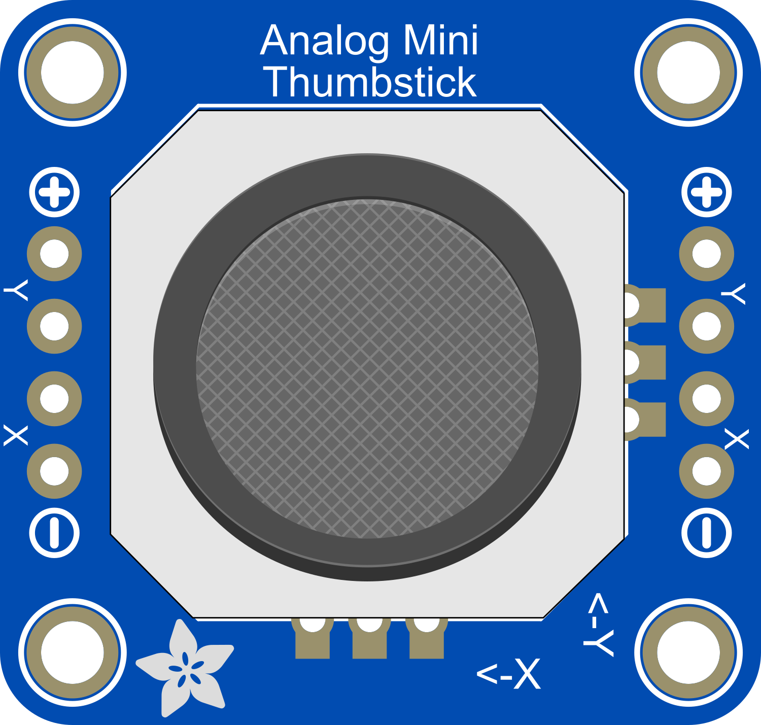
The Adafruit Mini Analog Thumbstick is a compact joystick module that offers precise two-axis control. It is an ideal input device for DIY electronics projects, including gaming consoles, remote controls, and robotics. Its small form factor and analog output make it versatile for various applications where user input is required for directional control.
Explore Projects Built with Adafruit Mini Analog Thumbstick
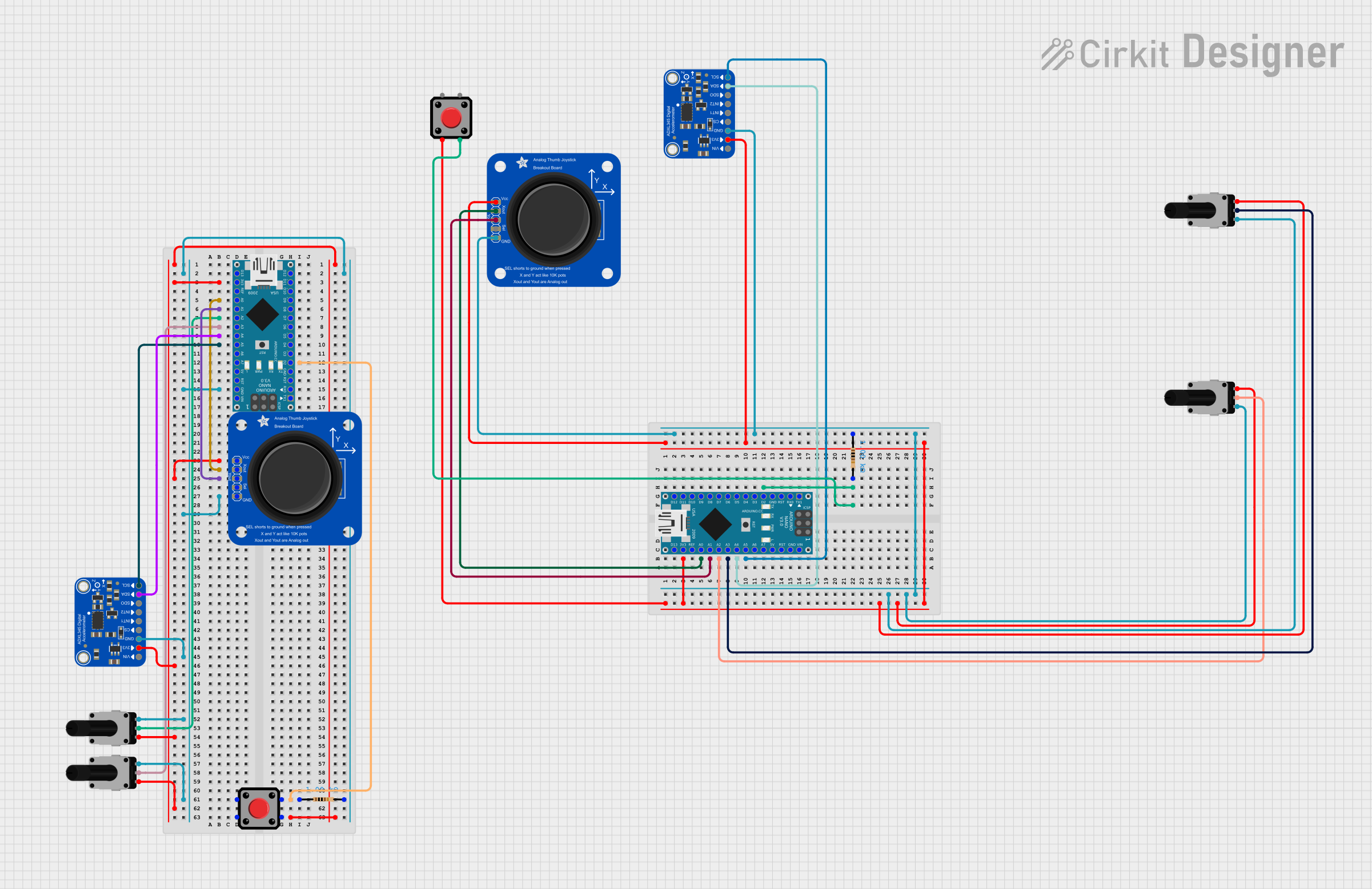
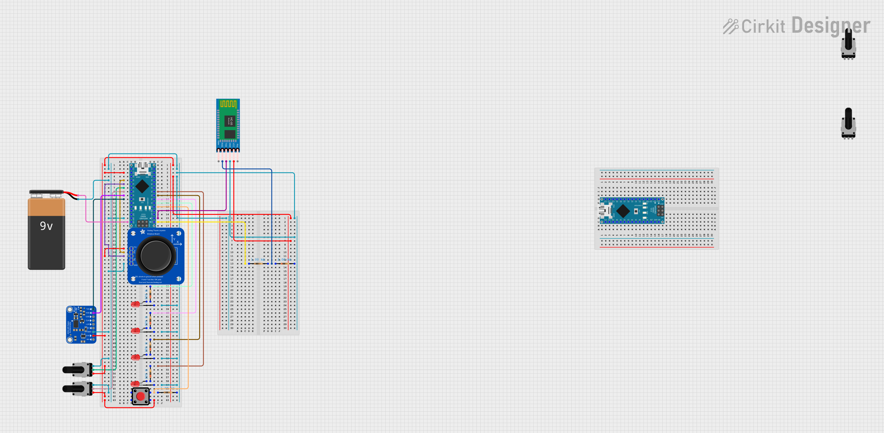
Explore Projects Built with Adafruit Mini Analog Thumbstick
Technical Specifications
Key Technical Details
- Voltage: 3.3V to 5V
- Current: 10mA (typical)
- X-Axis Range: 0 to 1023 (analog output)
- Y-Axis Range: 0 to 1023 (analog output)
- Dimensions: 26.5mm x 26.5mm x 32mm
Pin Configuration and Descriptions
| Pin Number | Name | Description |
|---|---|---|
| 1 | VCC | Power supply (3.3V to 5V) |
| 2 | GND | Ground connection |
| 3 | VRx | Analog output for X-axis |
| 4 | VRy | Analog output for Y-axis |
| 5 | SW | Switch (activated by pressing down on the joystick) |
Usage Instructions
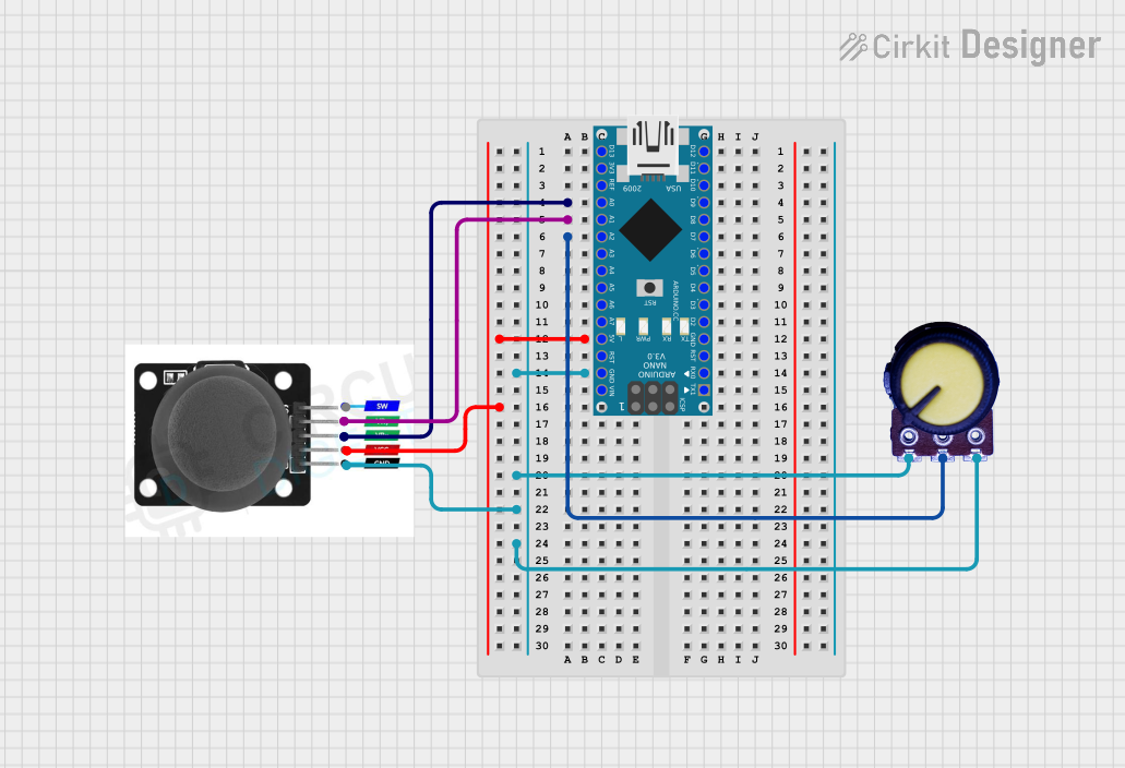
Connecting to a Circuit
- Connect the VCC pin to the power supply (3.3V or 5V) on your microcontroller board.
- Connect the GND pin to a ground pin on your microcontroller board.
- Connect the VRx pin to an analog input pin for reading the X-axis value.
- Connect the VRy pin to another analog input pin for reading the Y-axis value.
- Optionally, connect the SW pin to a digital input pin if you wish to use the built-in switch feature.
Important Considerations and Best Practices
- Ensure that the power supply voltage matches the requirements of the thumbstick to prevent damage.
- Use pull-up or pull-down resistors on the SW pin if your microcontroller does not have internal pull-up/down resistors.
- Calibrate the joystick in your software to account for any variances in the center position or range of motion.
- Avoid applying excessive force to the joystick to prevent physical damage.
Example Code for Arduino UNO
// Define the analog pins connected to the thumbstick
const int xAxisPin = A0;
const int yAxisPin = A1;
const int buttonPin = 2; // Digital pin connected to the thumbstick button

void setup() {
  // Initialize the serial communication
  Serial.begin(9600);
  // Set the button pin as an input with an internal pull-up resistor
  pinMode(buttonPin, INPUT_PULLUP);
}

void loop() {
  // Read the analog values from the thumbstick
  int xPosition = analogRead(xAxisPin);
  int yPosition = analogRead(yAxisPin);
  // Read the button state (pressed or not)
  bool buttonState = !digitalRead(buttonPin); // Invert because button is active low

  // Print the X and Y positions and button state to the serial monitor
  Serial.print("X: ");
  Serial.print(xPosition);
  Serial.print(" | Y: ");
  Serial.print(yPosition);
  Serial.print(" | Button: ");
  Serial.println(buttonState ? "Pressed" : "Not pressed");

  // Delay a bit before reading again
  delay(100);
}
Troubleshooting and FAQs
Common Issues
- Inaccurate Readings: If the joystick is not centered or giving inaccurate readings, ensure that it is properly calibrated in your software.
- No Response: Check the wiring and ensure that the VCC and GND pins are correctly connected.
- Button Not Working: Verify that the button pin is configured correctly and that you are using a pull-up or pull-down resistor as needed.
Solutions and Tips for Troubleshooting
- Double-check all connections and ensure that solder joints are solid and not causing intermittent connections.
- Use the
analogReference()function in Arduino if you need to adjust the reference voltage for the analog inputs. - Implement software debouncing if the button press is not stable or is registering multiple presses.
FAQs
Q: Can I use this thumbstick with a 3.3V system? A: Yes, the thumbstick can operate at 3.3V.
Q: How can I detect when the joystick is pressed down? A: The SW pin will go LOW when the joystick is pressed. Connect this pin to a digital input on your microcontroller and read its state.
Q: What is the life expectancy of the thumbstick? A: The life expectancy depends on usage, but it is designed to withstand repeated use within its specifications.
Q: Can I use this thumbstick for a commercial product? A: Yes, as long as you adhere to the component's specifications and usage guidelines, it can be integrated into commercial products.