How to Use Waveshare Led Matrix: Examples, Pinouts, and Specs
Introduction
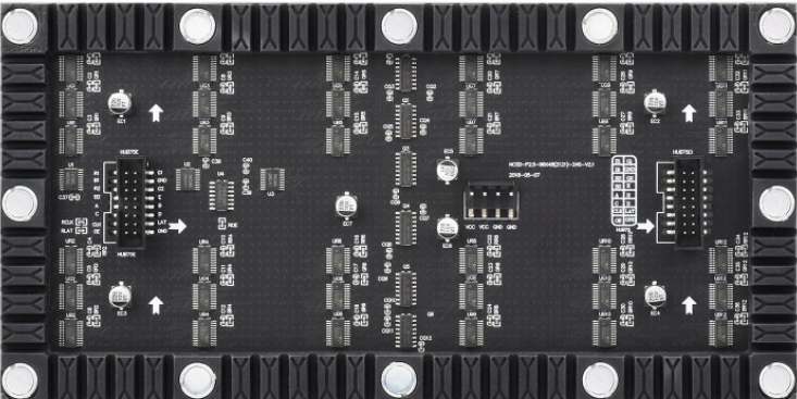
The Waveshare P2.5 92x48 Matrix is a versatile LED matrix display module designed for dynamic visualization of graphics and text. With its high-resolution 92x48 pixel grid, this module is ideal for applications requiring clear and vibrant visual output. It supports communication via SPI or I2C protocols, making it compatible with a wide range of microcontrollers, including Arduino and Raspberry Pi.
Explore Projects Built with Waveshare Led Matrix


Explore Projects Built with Waveshare Led Matrix
Common Applications
- Digital signage and advertising displays
- Scrolling text displays
- Graphical visualizations in embedded systems
- IoT dashboards and notifications
- Educational and hobbyist projects
Technical Specifications
The following table outlines the key technical details of the Waveshare P2.5 92x48 Matrix:
| Parameter | Value |
|---|---|
| Manufacturer | Waveshare |
| Part ID | P2.5 92x48 Matrix |
| Resolution | 92x48 pixels |
| Pixel Pitch | 2.5 mm |
| Communication Protocol | SPI / I2C |
| Operating Voltage | 5V DC |
| Power Consumption | ~2W (typical) |
| Dimensions | 230mm x 120mm x 10mm |
| Weight | ~150g |
Pin Configuration
The Waveshare LED Matrix features a standard pin header for interfacing. Below is the pin configuration:
| Pin | Name | Description |
|---|---|---|
| 1 | VCC | Power supply input (5V DC) |
| 2 | GND | Ground |
| 3 | DIN | Data input for SPI communication |
| 4 | CLK | Clock input for SPI communication |
| 5 | CS | Chip Select for SPI communication |
| 6 | ADDR | Address selection for I2C communication (optional) |
| 7 | SDA | Data line for I2C communication |
| 8 | SCL | Clock line for I2C communication |
Usage Instructions
Connecting the LED Matrix
- Power Supply: Connect the
VCCpin to a 5V DC power source and theGNDpin to ground. - Communication Protocol:
- For SPI: Connect
DIN,CLK, andCSto the corresponding SPI pins on your microcontroller. - For I2C: Connect
SDAandSCLto the I2C pins on your microcontroller. Use theADDRpin to set the I2C address if required.
- For SPI: Connect
- Library Installation: Download and install the Waveshare LED Matrix library or a compatible library for your microcontroller platform.
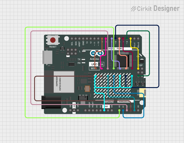
Example: Using with Arduino UNO
Below is an example of how to use the Waveshare LED Matrix with an Arduino UNO via SPI:
#include <SPI.h>

// Define SPI pins for the LED Matrix
#define DIN_PIN 11  // MOSI pin on Arduino UNO
#define CLK_PIN 13  // SCK pin on Arduino UNO
#define CS_PIN 10   // Chip Select pin

void setup() {
  // Initialize SPI communication
  SPI.begin();
  pinMode(CS_PIN, OUTPUT);
  digitalWrite(CS_PIN, HIGH);

  // Initialize the LED Matrix
  initializeMatrix();
}

void loop() {
  // Display a simple pattern on the LED Matrix
  displayPattern();
}

void initializeMatrix() {
  // Send initialization commands to the LED Matrix
  digitalWrite(CS_PIN, LOW);
  SPI.transfer(0x09); // Example command: Decode mode
  SPI.transfer(0x00); // No decode
  digitalWrite(CS_PIN, HIGH);

  digitalWrite(CS_PIN, LOW);
  SPI.transfer(0x0A); // Example command: Intensity
  SPI.transfer(0x0F); // Maximum brightness
  digitalWrite(CS_PIN, HIGH);

  digitalWrite(CS_PIN, LOW);
  SPI.transfer(0x0B); // Example command: Scan limit
  SPI.transfer(0x07); // Display all rows
  digitalWrite(CS_PIN, HIGH);

  digitalWrite(CS_PIN, LOW);
  SPI.transfer(0x0C); // Example command: Shutdown register
  SPI.transfer(0x01); // Normal operation
  digitalWrite(CS_PIN, HIGH);
}

void displayPattern() {
  // Example: Display a checkerboard pattern
  for (int row = 1; row <= 8; row++) {
    digitalWrite(CS_PIN, LOW);
    SPI.transfer(row);       // Select row
    SPI.transfer(0xAA);      // Example pattern: 10101010
    digitalWrite(CS_PIN, HIGH);
  }
}
Best Practices
- Ensure the power supply provides sufficient current for the LED Matrix.
- Use decoupling capacitors near the power pins to reduce noise.
- Avoid prolonged operation at maximum brightness to prevent overheating.
- Use proper pull-up resistors for I2C communication if required.
Troubleshooting and FAQs
Common Issues
No Display Output:
- Verify all connections, especially power and ground.
- Check if the communication protocol (SPI/I2C) is correctly configured.
- Ensure the LED Matrix is initialized properly in the code.
Flickering or Dim LEDs:
- Check the power supply for sufficient voltage and current.
- Inspect the SPI/I2C clock speed; it may need adjustment.
Incorrect Patterns or Text:
- Verify the data being sent to the LED Matrix.
- Ensure the row and column addressing in the code matches the matrix layout.
FAQs
Q: Can I daisy-chain multiple LED Matrices?
A: Yes, multiple Waveshare LED Matrices can be daisy-chained via SPI. Ensure proper addressing and sufficient power supply.
Q: What is the maximum viewing distance for this module?
A: The P2.5 pixel pitch is suitable for viewing distances of 2.5 meters or more.
Q: Does the module support PWM for brightness control?
A: Brightness can be controlled via software commands, but hardware PWM is not directly supported.
Q: Can I use this module with a Raspberry Pi?
A: Yes, the module is compatible with Raspberry Pi. Use the SPI or I2C interface and install the appropriate libraries.
By following this documentation, you can effectively integrate the Waveshare P2.5 92x48 Matrix into your projects for dynamic and engaging visual displays.